About EX Controller
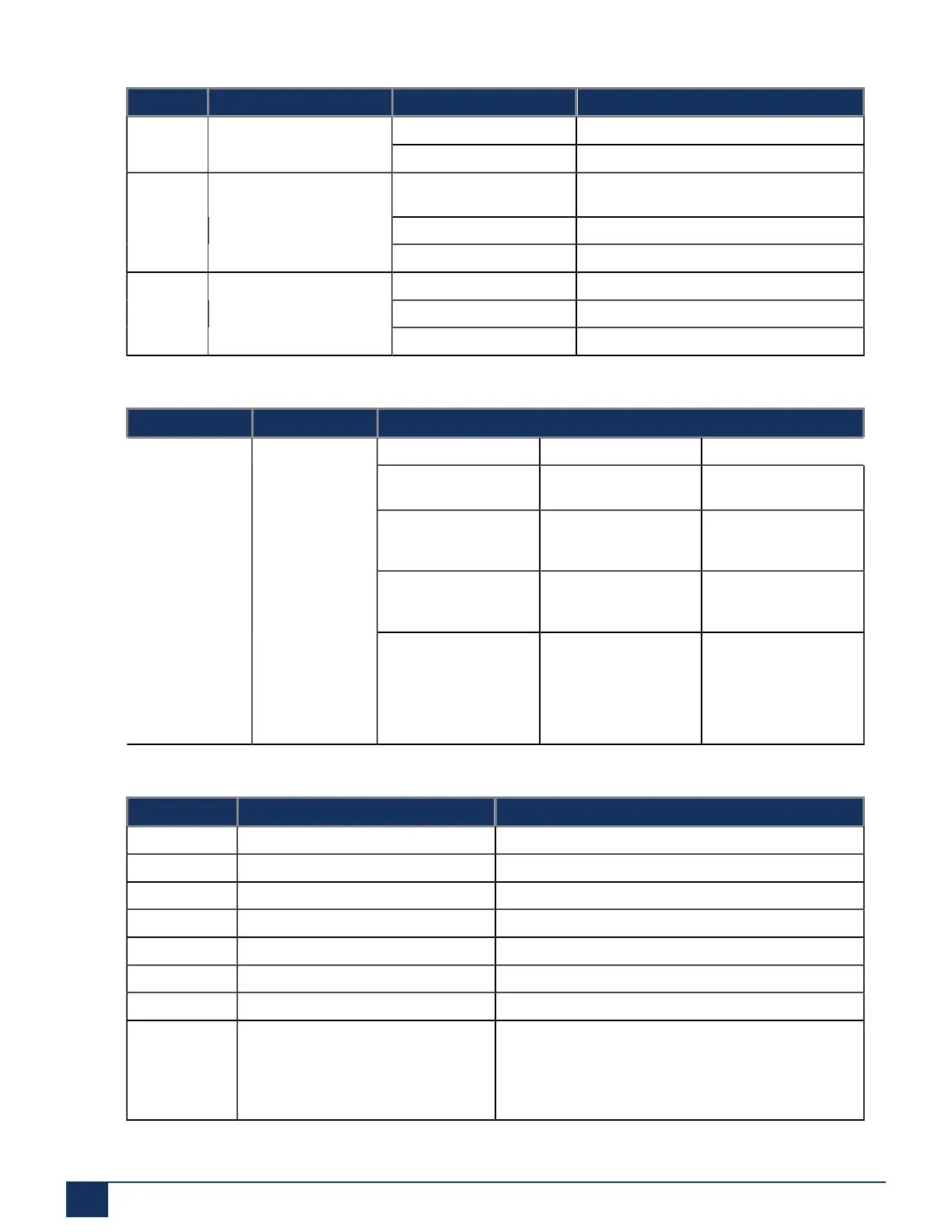
# LED LED State Description
Green 100 Mbps
Yellow 1000 Mbps
Green blinking, variable
rate
Connected with active network traffic.
Green, steady on Connected with no active network traffic.
14 ETH2/3/4/5/ext -Right LED
(activity)
Off Not connected
Off 10 Mbps
Green 100 Mbps
14 ETH2/3/4/5/ext -Left LED
(speed)
Yellow 1000 Mbps
Table 3: Switch
# SWITCH DESCRIPTION
Pressing Duration Result LED Pattern
2 to 6 seconds Restarts the EX Cont
roller unit.
Power LED blinking.
All other LEDs are off.
7 to 11 seconds Initiates a Partial Rese
t of the EX Controller u
nit.
All LEDs blinking one
cycle per second, 50%
duty.
12 to 16 seconds Initiates a Factory
Reset of the EX Cont
roller unit.
All LEDs steady on.
4 Reset/Default
17 seconds or more No action taken. A u
seful option if you have
accidentally pushed
the button and do not
want any action to be
performed.
All LEDs will turn off a
fter blinking and turn s
teady on.
Table 4: Connectors and Cards
# Connectors/Cards Description
6 USB1 USB connector
7 USB2 USB connector
8 SYNC IN 8 KHz TDM synchronization pulse input
9 SYNC OUT 8 KHz TDM synchronization pulse output
10 PRI card with PRI port RJ48 connector for ISDN-PRI connectivity
11 DSP CARD No connector available.
12 FXS card with FXS ports RJ11 connectors for traditional analog line devices.
13 ETH1 A 10/100/1000 BaseT Ethernet RJ45 connector for
access to a WAN.
Typically, not used for the deployment.
17 EX Controller Installation and Administration Guide
 Loading...