TA7104 /7108 Hardware Installation
155/1531-ANF 90114 C 2017-03-08
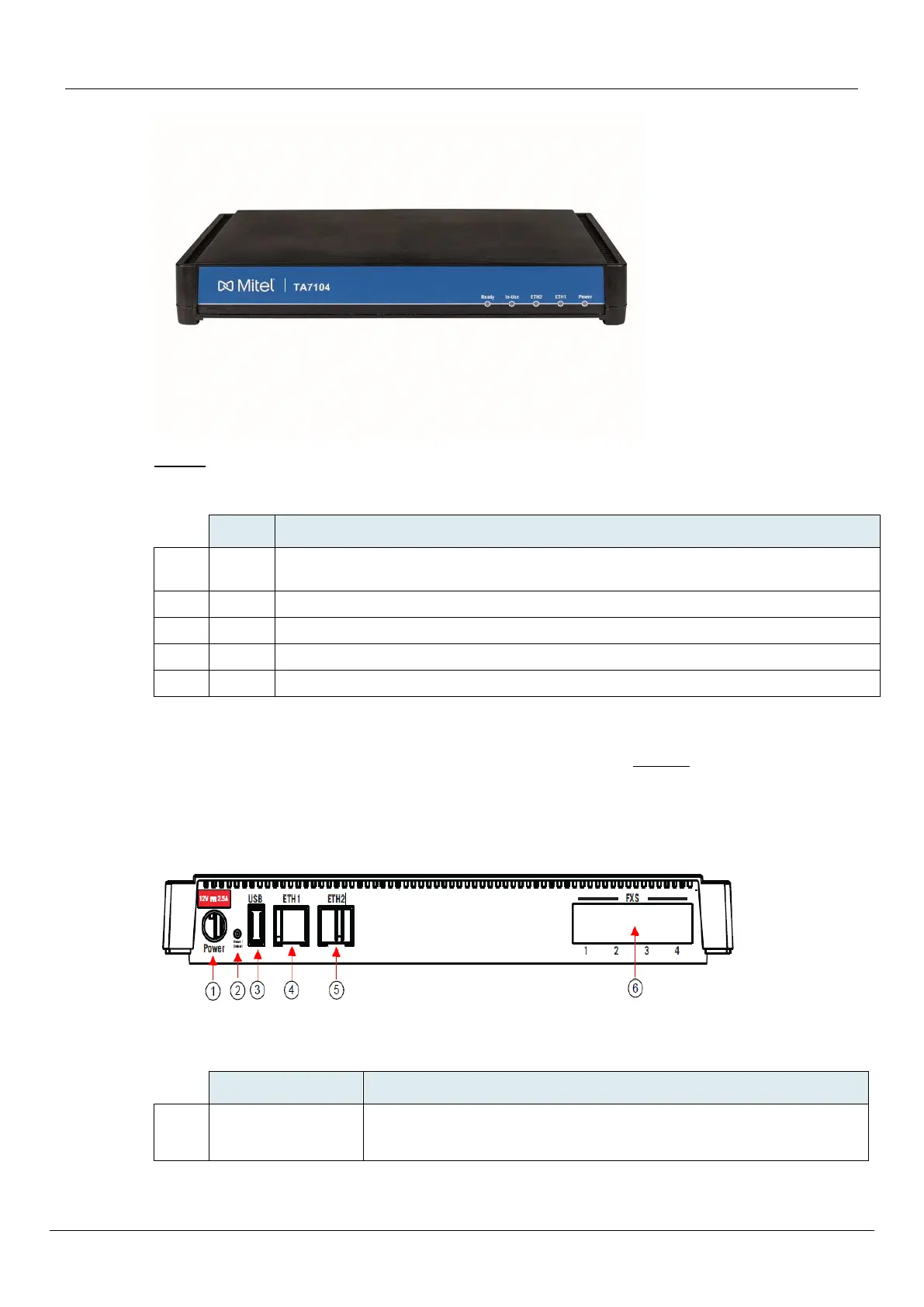
Table 2 describes the indicators on the front panel of the TA7104.
Table 2: TA7104/7108 Front LEDs
When lit, the TA7104/7108 is ready to initiate or receive a call. The unit does not have
to be registered to a server.
When lit, at least one of the FXS/FXO lines is in use.
Provides the state of the network connected to the ETH2 connector.
Provides the state of the network connected to the ETH1 connector.
When lit, power is applied to the TA7104/7108 .
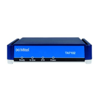
Rear Connectors
The TA7104/7108 has several connections that must be properly set. Figure 2 shows the rear panel of
the TA7104.
Standards Supported -ITU-T I.430 Basic user-network interface - Layer 1 specification (section 9).
Figure 2: TA7104 Rear Panel Connectors
Table 3 describes the rear panel connections (from left to right).
External 12 Vdc power supply. The TA7104/7108 uses
• a 1.5A power supply.