Installation of the inverter and enclosure design
INSTALLATION AND WIRING
17
2
2.3 Installation of the inverter and enclosure design
When designing or manufacturing an inverter enclosure, determine the structure, size, and device layout of the enclosure by
fully considering the conditions such as heat generation of the contained devices and the operating environment. An inverter
uses many semiconductor devices. To ensure higher reliability and long period of operation, operate the inverter in the
ambient environment that completely satisfies the equipment specifications.
2.3.1 Inverter installation environment
The following table lists the standard specifications of the inverter installation environment. Using the inverter in an
environment that does not satisfy the conditions deteriorates the performance, shortens the life, and causes a failure. Refer to
the following points, and take adequate measures.
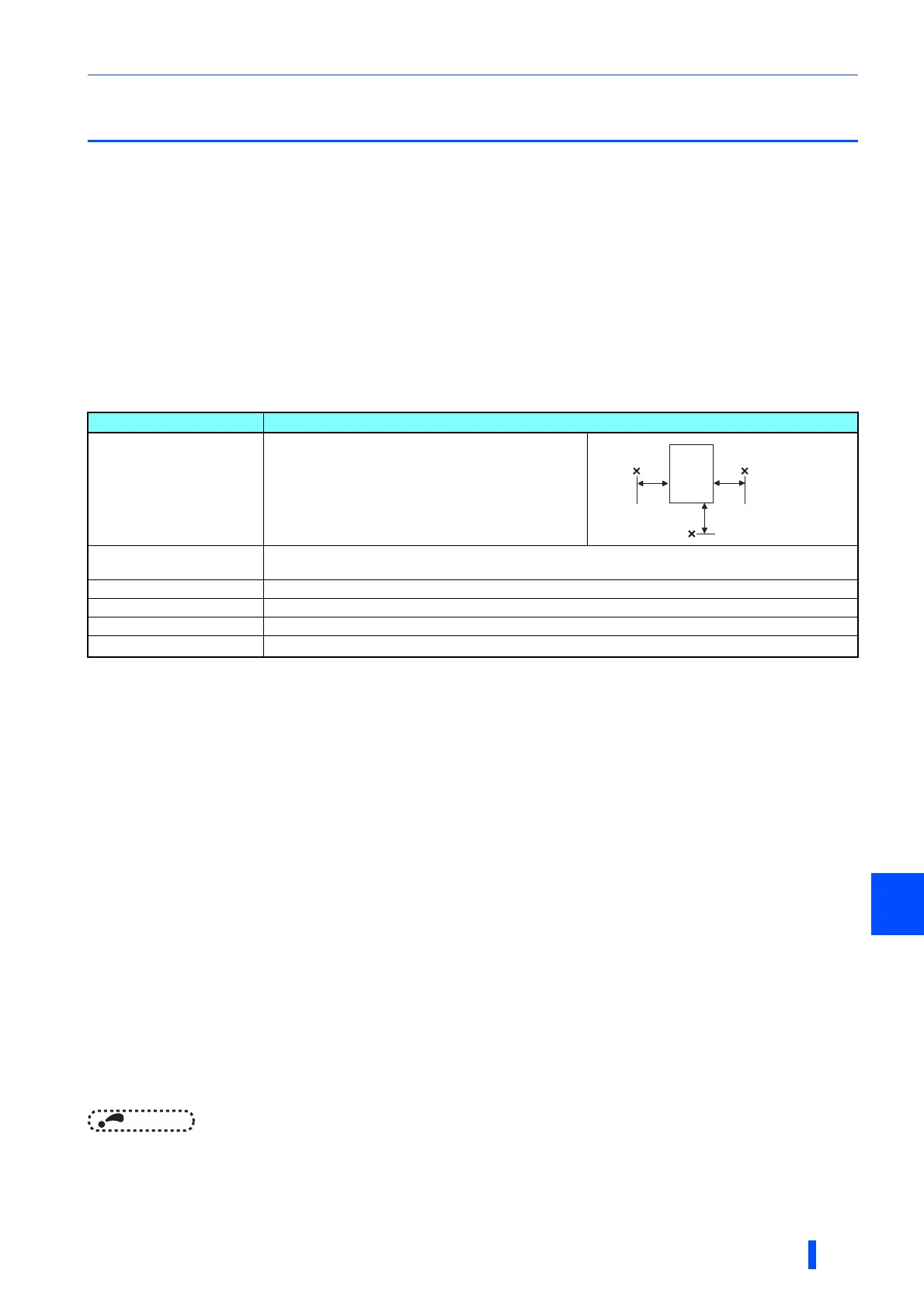
Standard environmental specifications of the inverter
Temperature applicable for a short time, e.g. in transit.
For the installation at an altitude above 1000 m (up to 2500 m), consider a 3% reduction in the rated current per altitude increase of 500 m.
Temperature
The permissible surrounding air temperature of the inverter is between -10°C and +50°C. Always operate the inverter within
this temperature range. Operation outside this range will considerably shorten the service lives of the semiconductors, parts,
capacitors and others. Take the following measures to keep the surrounding air temperature of the inverter within the specified
range.
(a) Measures against high temperature
• Use a forced ventilation system or similar cooling system. (Refer to page 20.)
• Install the enclosure in an air-conditioned electric chamber.
• Block direct sunlight.
• Provide a shield or similar plate to avoid direct exposure to the radiated heat and wind of a heat source.
• Ventilate the area around the enclosure well.
(b) Measures against low temperature
• Provide a space heater in the enclosure.
• Do not power OFF the inverter. (Keep the start signal of the inverter OFF.)
(c) Sudden temperature changes
• Select an installation place where temperature does not change suddenly.
• Avoid installing the inverter near the air outlet of an air conditioner.
• If temperature changes are caused by opening/closing of a door, install the inverter away from the door.
• For the amount of heat generated by the inverter unit, refer to page 19.
Item Description
Surrounding air temperature -10 to +50°C (non-freezing)
Surrounding air humidity
With circuit board coating (conforming to IEC60721-3-3 3C2/3S2) 95% RH or less (non-condensing)
Without circuit board coating 90% RH or less (non-condensing)
Storage temperature -20 to + 65°C
Atmosphere Indoors (free from corrosive gas, flammable gas, oil mist, dust and dirt)
Altitude Maximum 1,000 m
Vibration
2.9 m/s
2
or less at 10 to 55 Hz (directions of X, Y, Z axes)
Measurement
position
Measurement
position
Inverter
5 cm
5 cm
5 cm