Terminal connection diagrams
32
INSTALLATION AND WIRING
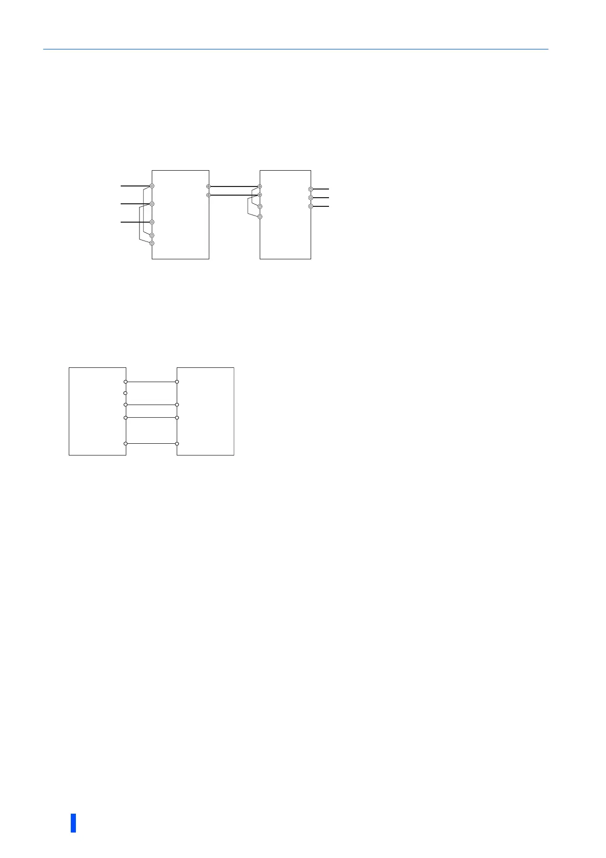
Wiring between the converter units and the inverters
Main circuit terminal
• Wire terminal P (+) on the converter unit to terminal P on the inverter, and do likewise for terminal N (-). Pair the masters
or the slaves (1 with 1 or 2.with 2). Otherwise, the converter unit and the inverter may be damaged.
• Use cables of 50 m or shorter each to connect the converter unit and the inverter (for terminal P or N).
• For information about the gauge of cable for terminal P or N, refer to page 35.
Do not install an MCCB for terminal P or N. Ensure correct connection in polarity of terminals P and N; which may damage the inverter.
Control circuit terminal
• Wiring both of control circuits in the master converter unit and the master inverter is required. Wire correctly to ensure
the command transmission from the converter unit to the inverter. Otherwise, the converter unit and the inverter may be
damaged.
• Use cables of 30 m or shorter each to wire the control circuits.
For the terminal used for the X10 signal input, set "10" in any of Pr.178 to Pr.189 (Input terminal function selection) to assign the function.
(The X10 signal is assigned to terminal MRS in the initial setting.
The state of contact at terminal MRS is initially set to be normally closed (NC). To change the contact state to normally open (NO), set Pr.599 =
"0".)
For the terminal used for the X11 signal input, set "11" in any of Pr.178 to Pr.189 (Input terminal function selection) to assign the function.
$$The X11 signal is usable to store the inverter state at an instantaneous power failure occurred in communication operation in which the start
command is transmitted only once (such as RS-485 communication) if the state storage is set to be enabled in advance.
It is mandatory to wire terminal RDA on the converter unit to terminal MRS (X10) on the inverter and to wire terminal SE on the converter unit to
terminal SD (sink logic) on the inverter. Otherwise, the converter unit may be damaged.
InverterConverter unit
R1/L11
S1/L21
R/L1
S/L2
T/L3
U
V
W
R1/L11
S1/L21
P/+P/+
N/-
N/-
∗1
To motor
Power supply
X11
RES
SD
IPF
RSO
SE
MRS(X10)
RDA
∗3
∗3
∗2
∗1
RDB
Converter unit Inverter