[ IV Electrical Wiring Diagram ]
- 82 -
HWE1708A GB
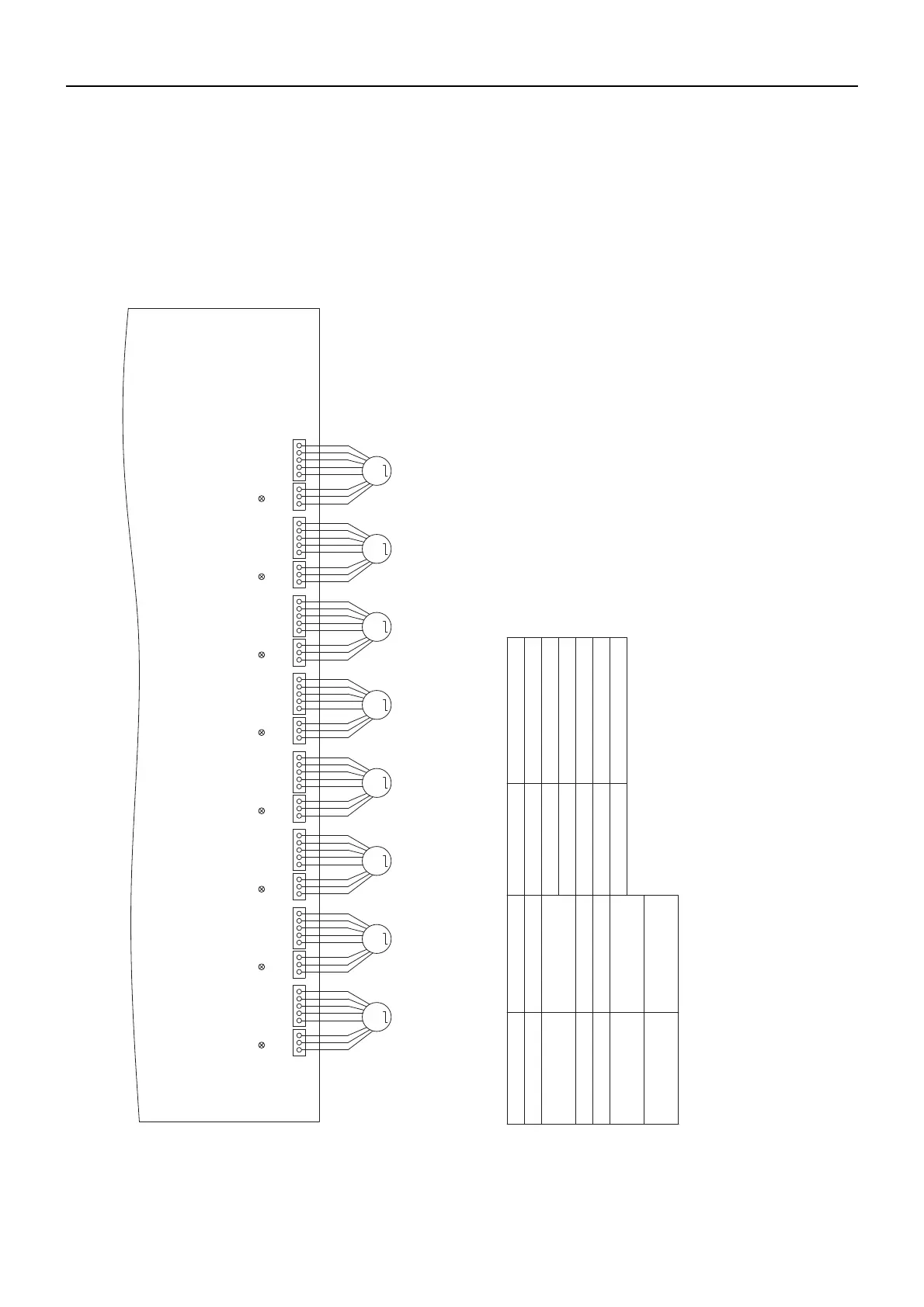
(2) CMB-WM108V-AA (Detail of X section)
(Red)(Red) (Yellow)(Yellow)
(Red) (Red) (Yellow) (Yellow)
(Red) (Red)
MMMMMMMM
CN202 CN201
CN203CN204 CN205CN206
CN207CN208
CN210 CN209 CN212 CN211
CN214 CN213
CN216 CN215
VB3a VB3b VB3c VB3d VB3e VB3f VB3g VB3h
operation operation operation operation operation operation operation operation
LEV1~3
TH11~16,TH32~35,
TH31a~h
ACL
PS1,PS3
Pressure sensor
AC reactor
Thermister sensor
Expansion valve
Terminal block
(for power source)
Terminal block
(for Transmission)
Fuse AC250V 6.3A F
F001
Solenoid valveSV1
21S4Ma,21S4Mb 4 way valve
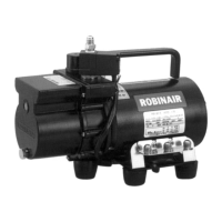
WP1,WP2
Pump
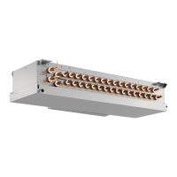
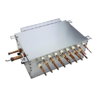
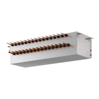
VB3a~h
Valve block
FS
Float switch
LD1:CPU in LD1:CPU in LD1:CPU in LD1:CPU in LD1:CPU in LD1:CPU in LD1:CPU in LD1:CPU in
Symbol
(Symbol explanation)
Name
TB01
TB02
NOTE:1.TB02 is transmission terminal block.
Never connect power line to it.
2.The initial set values of switch on
Control Board are as follows.
SW1:0
SW2:0
Name
Symbol
32132145 43213215 4321321543213215 432132154321
3
2
1
54321321543213215
0000002394.book 82 ページ 2023年9月7日 木曜日 午後4時2分
 Loading...