44
WT07417X01
10-2. Pulse signal input function
Using pulse signals directly input from metering device such as watt-hour meter, billing data and energy
management data will be obtained based on the cumulative number of pulse signal input.
Note
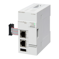
● To input pulse signals directly from the metering device to the EW-50, use the connector connected to the EW-50. (A
precision screwdriver for M1 screws is required.).
Usability of a built-in PI controller for each function
Function AE-200 AE-50 EW-50
Apportioned electricity billing function (option) x
*1
V
*2
V
*2
Energy management V V V
Demand function (option) V V V
(V): Usable, (x): Not usable
*1 A built-in PI controller on the AE-200 cannot be used for an apportioned electricity billing function. Use a built-in PI controller on the AE-50 or
EW-50.
*2 Using a PI controller (PAC-YG60MCA) is recommended instead of a built-in PI controller on the AE-50/EW-50 when using an apportioned
electricity billing function. (Discrepancies may occur between the built-in PI controller reading and the actual electric energy because the
pulse input cannot be obtained during the AE-50/EW-50 power failure, shutoff process, and software update.)
(1) Pulse signal input specifications
CN7 Signal
No. 7, 8 Metering device 4 (count input)
No. 5, 6 Metering device 3 (count input)
No. 3, 4 Metering device 2 (count input)
No. 1, 2 Metering device 1 (count input)
(2) Recommended circuit
P4
P3
P2
P1
(8)
(7)
(6)
(5)
(4)
(3)
(2)
(1)
CN7
A voltage of 12 VDC is applied to CN7. Do not apply a power
voltage from any other power source.
Contact rating
Rated voltage: 12 VDC
Rated current: 0.1 A or above
Minimum applied load: DC 1 mA
Note
● The total length of the lead wire and extension cable should not exceed 100 m (328 ft). (Use an extension cable of 0.3 mm
2
or thicker.)
● Cut the excess cable near the connector, and insulate the end of the unused cable with tape.
● Do not run the signal input cable adjacent to the M-NET transmission and power cables. Do not let the cable form a loop.
● Peel off the sheath to 6 ±1 mm (4/16 ±1/16 in) from the end, and securely insert the cable into the terminal.
● Leave adequate slack in the cables so that the weight of them will not strain the terminal connectors. Use cable clamps or
trunk terminals as necessary.
12 VDC
AE-200/AE-50/EW-50
Max.
100 m (328 ft)
 Loading...