Do you have a question about the Mitsubishi Electric FR-E700EX and is the answer not in the manual?
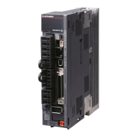
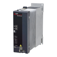
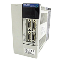
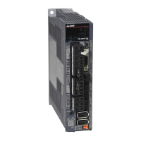
Check the drive unit and capacity plate on the front cover and rating plate to ensure product agreement and integrity.
Details on AC power supply, reactors, noise filters, magnetic contactors, and other peripheral devices for the drive unit.
Instructions for safely removing and reinstalling the front cover and wiring cover of the drive unit.
Guidelines for designing and manufacturing drive unit enclosures, considering heat, environment, and layout.
Terminal connection diagrams for speed control, position control, and external terminals.
Specifications for main circuit terminals, including power supply and motor wiring arrangements.
Details on control circuit terminals, including input signals, output signals, and communication interfaces.
Instructions for connecting external brake resistors, brake units, and other option units.
Measures to suppress electromagnetic noise and leakage currents to prevent malfunction and damage.
Guidelines for installing reactors to prevent excessive peak current and protect the converter circuit.
Recommendations for using magnetic contactors on the drive unit's input and output sides for safety.
General precautions for installation, wiring, operation, and handling to ensure product longevity and safety.
Methods for implementing failsafe by combining drive unit status signals and external backups.
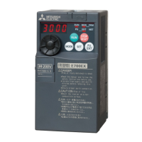
Overview of the operation panel, including indicators, buttons, and their functions for setting and monitoring.
Comprehensive list of parameters, their settings, references, and applicability to different motor control modes.
Detailed explanation of PM sensorless vector control, including parameter settings and operation.
Information on adjusting speed control parameters, feed forward control, and troubleshooting speed issues.
Configuration and adjustment of position control parameters, including gain, electronic gear, and home position return.
Methods for adjusting torque limit, PM control torque boost, and other torque-related parameters.
Setting maximum/minimum rotation speeds and avoiding mechanical resonance using speed jump.
Configuring speed settings using multi-speed operations, jog operations, and remote setting functions via external terminals.
Adjusting acceleration/deceleration times and selecting appropriate patterns like linear or S-pattern.
Procedures for selecting the correct motor and applying protection mechanisms like overheat protection.
Configuration of braking, zero speed control, pre-excitation, servo-ON, and servo lock functions.
Mapping external signals to drive unit functions for inputs and outputs.
Selecting and displaying various operational parameters on the panel, terminal FM, and communication.
Configuring drive unit behavior and retry functions when faults occur.
Setting speed using analog voltage or current inputs, including calibration and noise elimination.
Implementing measures to prevent incorrect operations and restrict parameter changes.
Choosing between PU, external, network, and combined operation modes for the drive unit.
Setting up communication via PU connector, RS-485, USB, Modbus-RTU, and Mitsubishi inverter protocols.
Utilizing PID control for process applications and regeneration avoidance functions.
Functions for cooling fan control, part life display, maintenance timers, free parameters, and fault initiation.
Configuring rotation direction, setting dial behavior, buzzer, and LCD contrast via the operation panel.
Procedures for clearing specific parameters or resetting all parameters to their initial values.
Displaying and setting parameters that have been changed from their initial values.
Methods for checking and clearing the drive unit's stored faults history.
Procedures for resetting the drive unit after a fault or warning occurs.
A comprehensive list of fault and alarm codes displayed on the operation panel with corresponding references.
Troubleshooting guide detailing common causes for errors, warnings, and faults, with recommended corrective actions.
Mapping between alphanumeric characters displayed on the operation panel and actual digital representations.
Step-by-step checks for common issues like motor not starting, abnormal noise, or incorrect speed.
Guidelines for daily and periodic inspections to prevent faults and ensure reliable operation.
Methods and recommended instruments for measuring electrical characteristics of the drive unit.
Electrical ratings for three-phase 200V power supply, including current, voltage, frequency, and protective structure.
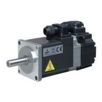
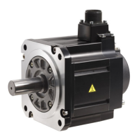
Comparative specifications for MM-GKR and S-PM geared motors, covering control, speed, and communication.
Mechanical dimensions and mounting details for drive units, parameter units, and operation panels.
Specific precautions for using MM-GKR motors, including restrictions and motor structure comparisons.
Safety guidelines for operating and handling S-PM geared motors, including installation and operation precautions.
Details on changes and additions to specifications for drive units manufactured from January 2014 onwards.
Alphabetical index of terms and parameters for quick reference within the manual.
| Series | FR-E700EX |
|---|---|
| Type | Servo Drive |
| Protection Class | IP20 |
| Rated Output Current | Varies by model |
| Control Method | Vector Control |
| Communication Options | RS-485, CC-Link |
| Protection Features | Overcurrent, Overvoltage, Undervoltage, Short Circuit |
| Operating Temperature | -10°C to +50°C |
| Storage Temperature | -20 to 65 °C |
| Humidity | 95% RH or less (non-condensing) |
| Vibration Resistance | 5.9 m/s² |
| Weight | Varies by model (e.g., 0.5kg to 10kg) |