15
Installation
4
en
0.0
10.0
20.0
30.0
40.0
50.0
60.0
70.0
80.0
0.0 5.0 10.0 15.0 20.0 25.0 30.0 35.0 40.0 45.0 50.0
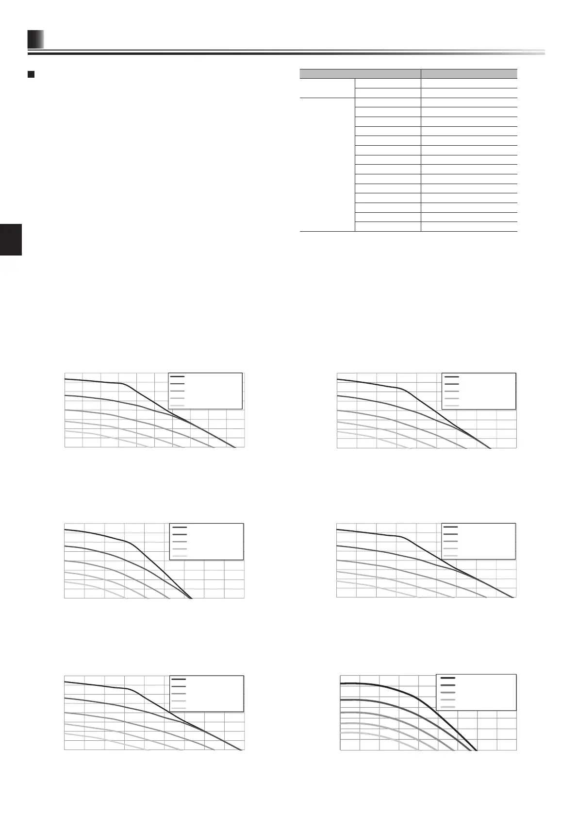
<Figure 4.3.4>
EHPX series
Flow rate [L/min]
External static pressure [kPa]
Speed 5 (Default setting)
Speed 4
Speed 3
Speed 2
Speed 1
* If the water flow rate is less than the minimum flow rate setting of the flow
sensor(default 5.0L/min),, the ow rate error will be activated.
If the water ow rate exceeds 36.9 L/min, the ow speed will be greater than 2.0
m/s, which could erode the pipes.
Water Circulation Pump Characteristics
Pump speed can be selected by main remote controller setting (see <Figure 4.3.4
to 4.3.9>).
Adjust the pump speed setting so that the ow rate in the primary circuit is appropri-
ate for the outdoor unit installed (see Table 4.3.1). It may be necessary to add an
additional pump to the system depending on the length and lift of the primary circuit.
For outdoor unit model not listed in the <Table 4.3.1>, refer to Water ow rate
range in the specication table of outdoor unit Data Book. In such case, make sure
that the ow rate is greater than 5.0 L/min and less than 36.9 L/min.
<Second pump >
If a second pump is required for the installation please read the following carefully.
If a second pump is used in the system it can be positioned in 2 ways.
The position of the pump inuences which terminal of the FTC the signal cable
should be wired to. If the additional pump(s) have current greater than 1A please
use appropriate relay. Pump signal cable can either be wired to TBO.1 1-2 or
CNP1 but NOT both.
Option 1 (Space heating/cooling only)
If the second pump is being used for the heating circuit only then the signal cable
should be wired to TBO.1 terminals 3 and 4 (OUT2). In this position the pump can
be run at a different speed to the hydrobox’s in-built pump.
Option 2 (Primary circuit DHW and space heating/cooling)
If the second pump is being used in the primary circuit between the hydrobox and
the outdoor unit (Package system ONLY) then the signal cable should be wired to
TBO.1 terminals 1 and 2 (OUT1). In this position the pump speed MUST match
the speed of the hydrobox’s in-built pump.
Note: Refer to 5.2 Connecting inputs/outputs.
Water Circulation Pump Characteristics
0.0
10.0
20.0
30.0
40.0
50.0
60.0
70.0
80.0
0.0 5.0 10.0 15.0 20.0 25.0 30.0 35.0 40.0 45.0
<Figure 4.3.5>
ERSC series
Flow rate [L/min]
External static pressure [kPa]
Speed 5 (Default setting)
Speed 4
Speed 3
Speed 2
Speed 1
0.0
10.0
20.0
30.0
40.0
50.0
60.0
70.0
80.0
0.0 5.0 10.0 15.0 20.0 25.0 30.0 35.0 40.0 45.0
<Figure 4.3.6>
ERSD series
Flow rate [L/min]
External static pressure [kPa]
Speed 5 (Default setting)
Speed 4
Speed 3
Speed 2
Speed 1
0.0
10.0
20.0
30.0
40.0
50.0
60.0
70.0
80.0
0.0 5.0 10.0 15.0 20.0 25.0 30.0 35.0 40.0 45.0
<Figure 4.3.7>
EHSC series
Flow rate [L/min]
External static pressure [kPa]
Speed 5 (Default setting)
Speed 4
Speed 3
Speed 2
Speed 1
0.0
10.0
20.0
30.0
40.0
50.0
60.0
70.0
80.0
0.0 5.0 10.0 15.0 20.0 25.0 30.0 35.0 40.0 45.0
<Figure 4.3.8>
EHSD series
Flow rate [L/min]
External static pressure [kPa]
Speed 5 (Default setting)
Speed 4
Speed 3
Speed 2
Speed 1
E*SE series
0.0
20.0
40.0
60.0
80.0
100.0
120.0
140.0
0.0 10.0 20.0 30.0 40.0 50.0 60.0 70.0 80.0 90.0
<Figure 4.3.9>
Flow rate [L/min]
External static pressure [kPa]
Speed 5 (Default setting)
Speed 4
Speed 3
Speed 2
Speed 1
Outdoor heat pump unit Water ow rate range [L/min]
Packaged model PUHZ-WM85 10.0 - 25.8
PUHZ-WM112 14.4 - 32.1
Split model SUZ-SWM40 6.5 - 11.4
SUZ-SWM60 7.2 - 17.2
SUZ-SWM80 7.8 - 21.5
PUHZ-SW50 7.1 - 17.2
PUHZ-FRP71 11.5 - 22.9
PUHZ-SW75 10.2 - 22.9
PUHZ-SW100 14.4 - 32.1
PUHZ-SW120 20.1 - 36.9
PUHZ-SHW80 10.2 - 22.9
PUHZ-SHW112 14.4 - 32.1
PUHZ-SHW140 17.9 - 36.9
PUMY-P112 17.9 - 35.8
PUMY-P125 17.9 - 35.8
PUMY-P140 17.9 - 35.8
<Table 4.3.1>