23
System Set Up
5
en
F1 F2 F3 F4
To change the settings of your heating/cooling system please use the main re-
mote controller located on the front panel of the cylinder unit or hydrobox. The
following is a guide to viewing the main settings. Should you require more infor-
mation please contact your installer or local Mitsubishi Electric dealer.
Cooling mode is available for ERS series only. However,
Cooling mode is not avail-
able when the indoor unit is connected to PUHZ-FRP.
Main remote controller
B C D
E
A
12 11
1 32
10
9
4
7
6
5
15 14
13
8
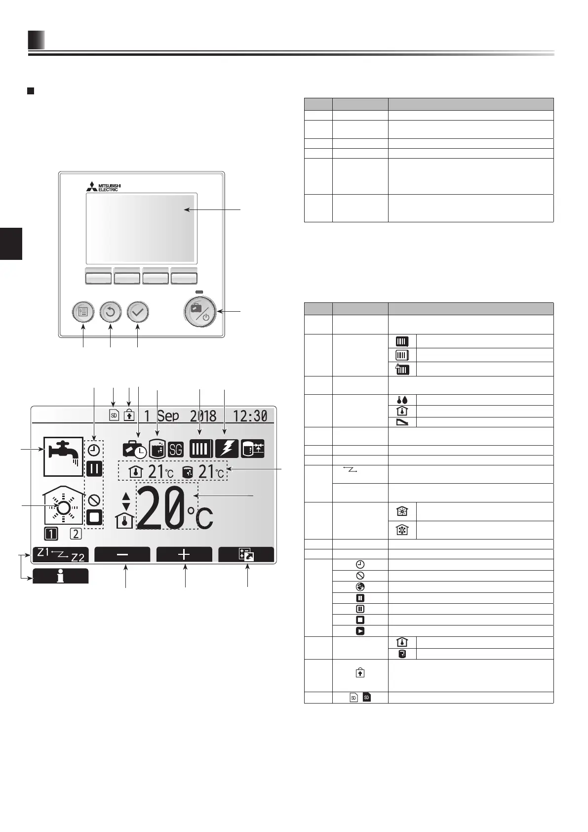
<Main remote controller parts>
Letter Name Function
A Screen Screen in which all information is displayed.
B Menu Access to system settings for initial set up and
modications.
C Back Return to previous menu.
D Conrm Used to select or save. (Enter key)
E Power/Holiday If system is switched off pressing once will turn
system ON. Pressing again when system is
switched on will enable Holiday Mode. Holding the
button down for 3 secs will turn the system off. (*1)
F1-4 Function keys Used to scroll through menu and adjust settings.
Function is determined by the menu screen visible
on screen A.
*1
When the system is switched off or the power supply is disconnected, the
indoor unit protection functions (e.g. freeze stat. function) will NOT operate.
Please beware that without these safety functions enabled the indoor unit
may potentially become exposed to damage.
<Main screen icons>
Icon Description
1 Legionella
prevention
When this icon is displayed ‘Legionella prevention
mode’ is active.
2 Heat pump
‘Heat pump’ is running.
Defrosting
Emergency heating
3 Electric heater When this icon is displayed the ‘Electric heaters’
(booster or immersion heater) are in use.
4 Target
temperature
Target ow temperature
Target room temperature
Compensation curve
5 OPTION Pressing the function button below this icon will dis-
play the option screen.
6 + Increase desired temperature.
7 - Decrease desired temperature.
8 Z1
Z2 Pressing the function button below this icon switch-
es between Zone1 and Zone2.
Information Pressing the function button below this icon displays
the information screen.
9 Space heating
(cooling) mode
Heating mode
Zone1 or Zone2
Cooling mode
Zone1 or Zone2
10 DHW mode Normal or ECO mode
11 Holiday mode
When this icon is displayed ‘Holiday mode’ activated.
12
Timer
Prohibited
Server control
Stand-by
Stand-by (*2)
Stop
Operating
13
Current
temperature
Current room temperature
Current water temperature of DHW tank
14
The Menu button is locked or the switching of the
operation modes between DHW and Heating opera-
tions are disabled in the Option screen. (*3)
15
SD memory card (NOT for the user) is inserted.
*2 This unit is in Stand-by whilst other indoor unit(s) is in operation by
priority.
*3 To lock or unlock the Menu, press the BACK and CONFIRM keys
simultaneously for 3 seconds.
Main screen
5.6 Main remote controller