1 2
3
4
5
6
TBO.1
LLL NNN
OUT1 OUT2 OUT3
LN
OUT9
LN
OUT15
L
1 2
3
4
5
6
TBO.2 TBO.3
1 2
3
4
5
6 7 8
1 2
3
4
6
5
TBO.4
N L L N
OUT5
OUT4
N L N L
OUT10 OUT16 OUT11 OUT12
N
OUT13Close Open
7 8
N L
OUT8
TBI.4
8 7
OUTA1
20
System Set Up
5
en
Note:
1. When the hydrobox is powered via outdoor unit, the maximum grand total current of (a)+(b) is 3.0 A.
2. Do not connect multiple water circulation pumps directly to each output (OUT1, OUT2, and OUT3). In such a case, connect them via (a) relay(s).
3. Do not connect water circulation pumps to both TBO.1 1-2 and CNP1 at the same time.
4. Connect an appropriate surge absorber to OUT10 (TBO.3 1-2) depending on the load at site.
5. Stranded wire should be processed with insulation-covered bar terminal (DIN46228-4 standard compatible type).
6. Use the same thing as the Signal input wire for OUTA1 wiring.
Item Name Model and specications
External output function Outputs wire
Use sheathed vinyl coated cord or cable.
Max. 30 m
Wire type: CV, CVS or equivalent
Wire size: Stranded wire 0.25 mm² to 1.5 mm²
Solid wire: 0.25 mm² to 1.5 mm²
Wiring specication and local supply parts
Outputs
Name Terminal block Connector Item OFF ON Signal/Max. current Max. total current
OUT1 TBO.1 1-2 CNP1 Water circulation pump 1 output
(Space heating/cooling & DHW)
OFF ON 230V AC 1.0A Max.
(Inrush current 40A Max.)
4.0A (a)
OUT2 TBO.1 3-4 — Water circulation pump 2 output
(Space heating/cooling for Zone1)
OFF ON 230V AC 1.0A Max.
(Inrush current 40A Max.)
OUT3 TBO.1 5-6 — Water circulation pump 3 output
(Space heating/cooling for Zone2) *1
OFF ON 230V AC 1.0A Max.
(Inrush current 40A Max.)
2-way valve 2b output *2
OUT14
—
CNP4 Water circulation pump 4 output (DHW) OFF ON 230V AC 1.0A Max.
(Inrush current 40A Max.)
OUT4
TBO.2 4-6 CNV1 3-way valve (2-way valve 1) output Heating DHW 230V AC 0.1A Max.
3.0A (b)
— CN851 3-way valve output
OUT5
TBO.2 1-2
— Mixing valve output *1 Stop
Close 230V AC 0.1A Max.
TBO.2 2-3 Open
OUT6 — CNBH 1-3 Booster heater 1 output OFF ON 230V AC 0.5A Max. (Relay)
OUT7 — CNBH 5-7 Booster heater 2 output OFF ON 230V AC 0.5A Max. (Relay)
OUT8 TBO.4 7-8 — Cooling signal output OFF ON 230V AC 0.5A Max.
OUT9 TBO.4 5-6 CNIH Immersion heater output OFF ON 230V AC 0.5A Max. (Relay)
OUT11 TBO.3 5-6 — Error output Normal Error 230V AC 0.5A Max.
OUT12 TBO.3 7-8 — Defrost output Normal Defrost 230V AC 0.5A Max.
OUT13 TBO.4 3-4 — 2-way valve 2a output *2 OFF ON 230V AC 0.1A Max.
OUT15 TBO.4 1-2 — Comp ON signal OFF ON 230V AC 0.5A Max.
OUT10 TBO.3 1-2 — Boiler output OFF ON
non-voltage contact
· 220-240V AC (30V DC)
0.5A or less
· 10mA 5V DC or more
—
OUT16 TBO.3 3-4 — Heating/Cooling thermo ON signal OFF ON
OUTA1 TBI.4 7-8 — Analog output — — 0-10V DC 5mA max. —
Do not connect to the terminals that are indicated as “—” in the “Terminal block” eld.
*1 For 2-zone temperature control.
*2 For 2-zone valve ON/OFF control.
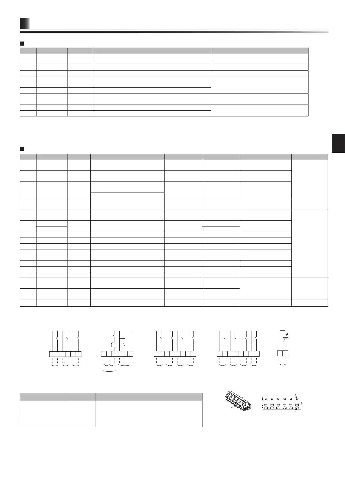
<Figure 5.2.2>
Tool
Tool
Conductor
Conductor
Outline view Top view
How to use TBO.1 to 4
Connect them using either way as shown above.
Thermistor inputs
Name Terminal block Connector Item Optional part model
TH1 — CN20 Thermistor (Room temp.) (Option) PAC-SE41TS-E
TH2 — CN21 Thermistor (Ref. liquid temp.) —
THW1 — CNW12 1-2 Thermistor (Flow water temp.) —
THW2 — CNW12 3-4 Thermistor (Return water temp.) —
THW5B — CNW5 3-4 Thermistor (DHW tank water temp.) (Option) *1 —
THW6 TBI.5 7-8 — Thermistor (Zone1 ow water temp.) (Option) *1
PAC-TH011-E
THW7 TBI.5 5-6 — Thermistor (Zone1 return water temp.) (Option) *1
THW8 TBI.5 3-4 — Thermistor (Zone2 ow water temp.) (Option) *1
PAC-TH011-E
THW9 TBI.5 1-2 — Thermistor (Zone2 return water temp.) (Option) *1
THWB1 TBI.6 7-8 — Thermistor (Boiler ow water temp.) (Option) *1
PAC-TH012HT-E
THW10 TBI.6 5-6 — Thermistor (Mixing tank water temp.)(Option1) *1
Ensure to wire thermistor wirings away from the power line and/or OUT1 to 16 wirings.
*1. The maximum length of the thermistor wiring is 30 m. When the wires are wired to adjacent terminals, use ring terminals and insulate the wires.
The length of the optional thermistors are 5 m. If you need to splice and extend the wirings, following points must be carried out.
1) Connect the wirings by soldering.
2) Insulate each connecting point against dust and water.