18
System Set Up
5
en
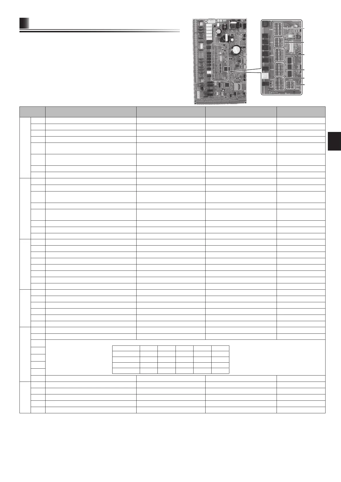
5.1 DIP Switch Functions
The DIP switch number is printed on the circuit board next to the relevant switch-
es. The word ON is printed on the circuit board and on the DIP switch block itself.
To move the switch you will need to use a pin or the corner of a thin metal ruler or
similar.
DIP switch settings are listed below in Table 5.1.1.
Only an authorised installer can change DIP switch setting under one’s own re-
sponsibility according to the installation condition.
Make sure to turn off both indoor unit and outdoor unit power supplies before
changing the switch settings.
DIP switch Function OFF ON
Default settings:
Indoor unit model
SW1
SW1-1 Boiler WITHOUT Boiler WITH Boiler OFF
SW1-2 Heat pump maximum outlet water temperature 55ºC 60ºC ON *1
SW1-3 DHW tank WITHOUT DHW tank WITH DHW tank OFF
SW1-4 Immersion heater WITHOUT Immersion heater WITH Immersion heater OFF
SW1-5 Booster heater WITHOUT Booster heater WITH Booster heater
OFF: E***-M*D
ON : E***-*M2/6/9D
SW1-6 Booster heater function For heating only For heating and DHW
OFF: E***-M*D
ON : E***-*M2/6/9D
SW1-7 Outdoor unit type Split type Packaged type ON
SW1-8 Wireless remote controller WITHOUT Wireless remote controller WITH Wireless remote controller OFF
SW2
SW2-1 Room thermostat1 input (IN1) logic change
Zone1 operation stop at thermostat short Zone1 operation stop at thermostat open
OFF
SW2-2 Flow switch1 input (IN2) logic change Failure detection at short Failure detection at open OFF
SW2-3 Booster heater capacity restriction Inactive Active
OFF: Except E***-VM2*D
ON : E***-VM2*D
SW2-4 — — — OFF
SW2-5
Automatic switch to backup heat source operation
(When outdoor unit stops by error)
Inactive Active *2 OFF
SW2-6 Mixing tank WITHOUT Mixing tank WITH Mixing tank OFF
SW2-7 2-zone temperature control Inactive Active *6 OFF
SW2-8 Flow sensor WITHOUT Flow sensor WITH Flow sensor ON
SW3
SW3-1 Room thermostat 2 input logic change
Zone2 operation stop at thermostat short Zone2 operation stop at thermostat open
OFF
SW3-2 Flow switch 2 and 3 input logic change Failure detection at short Failure detection at open OFF
SW3-3 — — — OFF
SW3-4 Electric energy meter WITHOUT Electric energy meter WITH Electric energy meter OFF
SW3-5 Heating mode function *3 Inactive Active ON
SW3-6 2-zone valve ON/OFF control Inactive Active OFF
SW3-7 Heat exchanger for DHW Coil in tank External plate HEX OFF
SW3-8 Heat meter WITHOUT Heat meter WITH Heat meter OFF
SW4
SW4-1 Multiple outdoor units control Inactive Active OFF
SW4-2 Position of multiple outdoor units control *7 Slave Master OFF
SW4-3 — — — OFF
SW4-4
Indoor unit only operation (during installation work) *4
Inactive Active OFF
SW4-5 Emergency mode (Heater only operation) Normal
Emergency mode (Heater only operation)
OFF *5
SW4-6 Emergency mode (Boiler operation) Normal Emergency mode (Boiler operation) OFF *5
SW5
SW5-1 — — — OFF
SW5-2 Advanced auto adaptation Inactive Active ON
SW5-3
SW5-4
SW5-5
SW5-6
SW5-7
SW5-8 — — — OFF
SW6
SW6-1 — — — OFF
SW6-2 — — — OFF
SW6-3 — — — OFF
SW6-4 Analog output signal (0-10V) Inactive Active OFF
SW6-5 — — — OFF
<Table 5.1.1>
<Figure 5.1.1>
SW1
SW3
SW4
SW2
SW5
SW5-3 SW5-4 SW5-5 SW5-6 SW5-7
E*SC-*M**D ON ON ON ON OFF
E*SD-*M**D ON OFF OFF ON OFF
E*SE-*M*ED OFF ON ON OFF ON
EHPX-*M**D OFF OFF OFF OFF OFF
Capacity code
SW6
Note: *1.
When the hydrobox is connected with a PUMY-P/SUHZ-SW outdoor unit of which maximum outlet water temperature is 55ºC, DIP SW1-2 must be changed to OFF.
*2. OUT11 will be available. For safety reasons, this function is not available for certain errors. (In that case, system operation must be stopped and only
the water circulation pump keeps running.)
*3 This switch functions only when the hydrobox is connected with a PUHZ-FRP outdoor unit. When another type of outdoor unit is connected, the
heating mode function is active regardless of the fact that this switch is ON or OFF.
*4. Space heating and DHW can be operated only in indoor unit, like an electric boiler. (Refer to “5.4 Indoor unit only operation”. )
*5. If emergency mode is no longer required, return the switch to OFF position.
*6. Active only when SW3-6 is set to OFF.
*7. Active only when SW4-1 is set to ON.