2
CN22
CN108
CN01
(BK)
1
3
CN3C
(BU)
CNPWM
(WH)
1
8
CN851
(BK)
1
5
CNRF
(WH)
CN105
(RD)
CNIT
(BU)
1
2
CN20
(RD)
TBI.1
LED3
LED4
TAB1
8
1
2
3
4
5
6
1
2
3
4
5
6
7
8
CNP1
(WH)
TBO.1
1
5
3
1
5
SW6
1
3
1
5
1
5
(BU)
1
LED2
1
SW1
8
1
SW2
8
1
SW3
1
SW4
6
8
1
SW5
LED1
1
3
1
3
CNP4
(RD)
TBO.2
1
2
3
4
5
6
TBO.3
CNV1
(WH)
1
3
5
1
2
3
4
5
6
7
8
TBO.4
CNIH
(OG)
1
3
CNBHT
(BK)
1
3
CNBC
(GY)
1
3
CNBH
(WH)
1
3
5
7
CN21
(YE)
1
3
CNW12
(RD)
1
4
CNW5
(BU)
1
4
1
4
CN1A
(WH)
68 7
5
4 3
2
1
TBI.2
68 7
5
4 3
2
1
TBI.3
68 7
5
4 3
2
1
TBI.4
68 7
5
4 3
2
1
TBI.5
68 7
5
4 3
2
1 68 7
5
4 3
2
1
TBI.6
1
4
CN401
(WH)
19
System Set Up
5
en
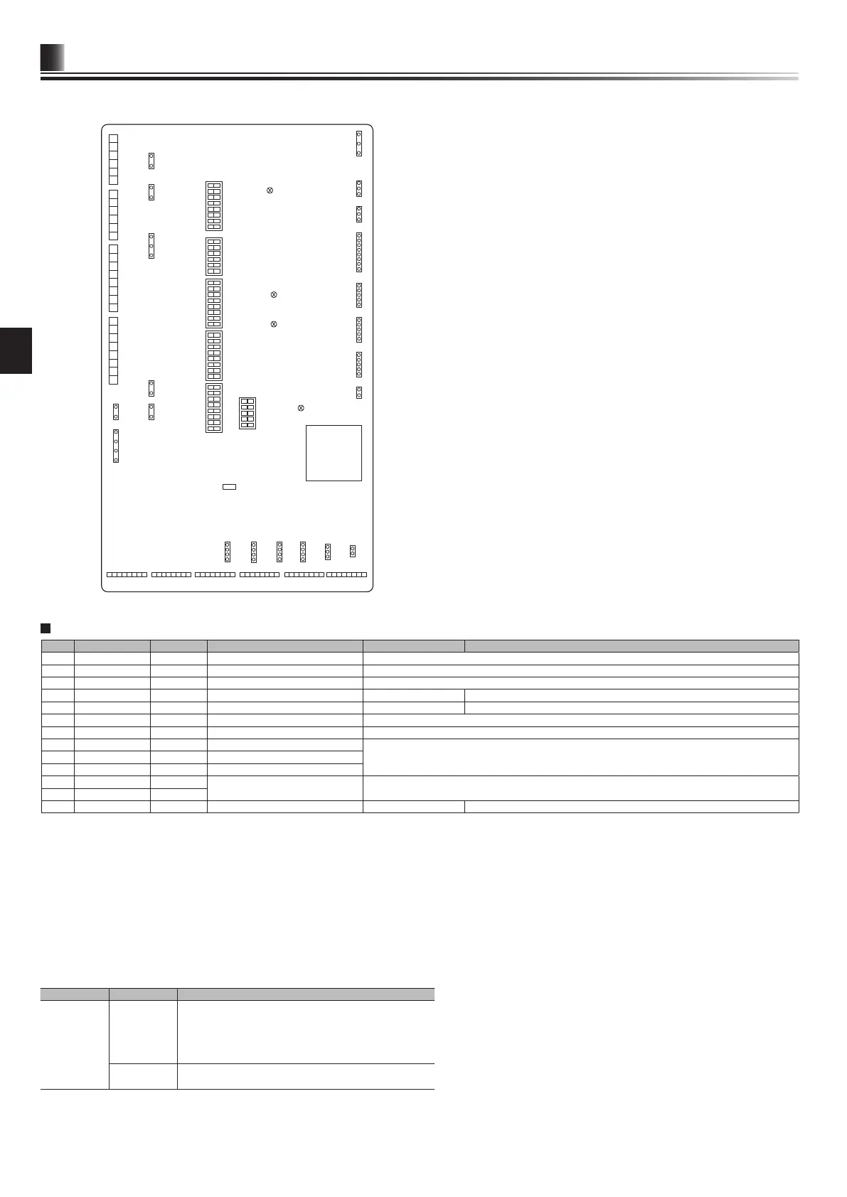
5.2 Connecting inputs/outputs
<Figure 5.2.1>
Signal inputs
Item Name Model and specications
Signal input
function
Signal input
wire
Use sheathed vinyl coated cord or cable.
Max. 30 m
Wire type: CV, CVS or equivalent
Wire size: Stranded wire 0.13 mm² to 0.52 mm²
Solid wire: ø0.4 mm to ø0.8 mm
Switch Non-voltage “a” contact signals
Remote switch: minimum applicable load 12V DC, 1mA
Wiring specication and local supply parts
Name Terminal block Connector Item OFF (Open) ON (Short)
IN1 TBI.1 7-8 — Room thermostat 1 input *1 Refer to SW2-1 in <5.1 DIP Switch Functions>.
IN2 TBI.1 5-6 — Flow switch 1 input Refer to SW2-2 in <5.1 DIP Switch Functions>.
IN3 TBI.1 3-4 — Flow switch 2 input (Zone1) Refer to SW3-2 in <5.1 DIP Switch Functions>.
IN4 TBI.1 1-2 — Demand control input Normal Heat source OFF/ Boiler operation *3
IN5 TBI.2 7-8 — Outdoor thermostat input *2 Standard operation Heater operation/ Boiler operation *3
IN6 TBI.2 5-6 — Room thermostat 2 input *1 Refer to SW3-1 in <5.1 DIP Switch Functions>.
IN7 TBI.2 3-4 — Flow switch 3 input (Zone2) Refer to SW3-2 in <5.1 DIP Switch Functions>.
IN8 TBI.3 7-8 — Electric energy meter 1
*4IN9 TBI.3 5-6 — Electric energy meter 2
IN10 TBI.2 1-2 — Heat meter
IN11 TBI.3 3-4 —
Smart grid ready input *5
IN12 TBI.3 1-2 —
INA1 TBI.4 1-3 CN1A Flow sensor — —
*1. Set the ON/OFF cycle time of the room thermostat for 10 minutes or more; otherwise the compressor may be damaged.
*2. If using outdoor thermostat for controlling operation of heaters, the lifetime of the heaters and related parts may be reduced.
*3. To turn on the boiler operation, use the main remote controller to select “Boiler” in “External input setting“ screen in the service menu.
*4. Connectable electric energy meter and heat meter
● Pulse type Voltage free contact for 12V DC detection by FTC (TBI.2 1 pin, TBI.3 5 and 7 pins have a positive voltage.)
● Pulse duration Minimum ON time: 40ms
Minimum OFF time: 100ms
● Possible unit of pulse 0.1 pulse/kWh 1 pulse/kWh 10 pulse/kWh
100 pulse/kWh 1000 pulse/kWh
Those values can be set by the main remote controller. (Refer to the menu tree in " Main remote controller".)
*5. As for the smart grid ready, refer to "5.5 Smart grid ready".
Note:
Stranded wire should be processed with insulation-covered bar terminal (DIN46228-4 standard compatible type).