8
Technical Information
3
en
Note
• Be sure to follow your local regulations to perform system conguration of the DHW connections.
• DHW connections are not included in the hydrobox package. All required parts are to be sourced
locally.
• To enable draining of the hydrobox an isolating valve should be positioned on both the inlet and
outlet pipework.
• Be sure to install a strainer on the inlet pipe work to the hydrobox.
• Suitable drain pipework should be attached to all relief valves in accordance with your country's
regulations.
• A backow prevention device must be installed on water supply pipework (IEC 61770).
• When using components made from different metals or connecting pipes made of different metals
insulate the joints to prevent a corrosive reaction taking place which will damage the pipework.
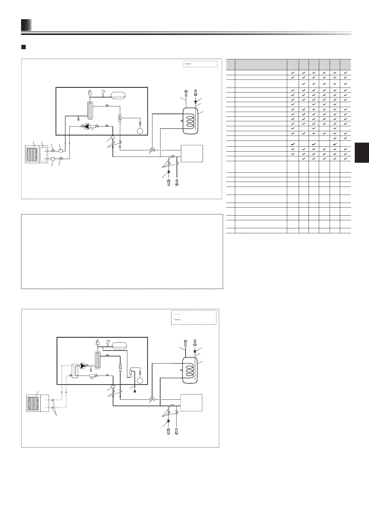
Water circuit diagram
No. Part name
EHPX-
*M*D
EHS*-
MED
EHS*-
*M*D
EHSC-
*M*ED
ERS*-
VM2D
ERSC-
MED
1 Control and electrical box
2
Main remote controller
3
Plate heat exchanger
(Refrigerant - Water)
-
4
Water circulation pump 1
5
Pump valve
6
Drain cock (Primary circuit)
7
Booster heater 1, 2
- -
8
Flow sensor
9
Manometer
10
Pressure relief valve (3 bar)
11
Automatic air vent
12
Expansion vessel
- - -
13
Strainer valve
14
Drain pan
- - - -
15
Pressure relief valve (5 bar)
- - -
16
THW1
17
THW2
18
TH2
-
19
THW5B
(Optional part PAC-TH011TK2-E
or PAC-TH011TKL2-E)
- - - - - -
20
Outdoor unit
- - - - - -
21
Drain pipe (Local supply)
- - - - - -
22
3-way valve (Local supply)
- - - - - -
23
DHW indirect unvented tank
(Local supply)
- - - - - -
24
Cold water inlet pipe
(Local supply)
- - - - - -
25
DHW outlet pipe (Local supply)
- - - - - -
26
Back ow prevention device
(Local supply)
- - - - - -
27
Isolating valve (Local supply)
- - - - - -
28
Magnetic lter (Local supply)
(Recommended)
- - - - - -
29
Strainer (Local supply)
- - - - - -
<Table 3.5>
*1 Refer to the following section [Local system].
<Figure 3.5>
Pa
19
23
26
24
25
26
27
24
7
6
5
8
9
11
12
13
16
17
22
28
3
20
27
29
29
27
4
15
<EHPX> (Packaged model system)
Water
supply
DHW
Drain
Cold
water
Water pipe
Hydrobox
Local
system *1
<Figure 3.6>
P
19
20
23
26
24
25
26
27
27
5
3
18
9
10
11
12
13
16
17
21
22
28
4
6
7
8
15
<EHS*> (Split model system)
<ERS*> (Split model system for heating and cooling)
Local
system *1
Refrigerant pipe
Water
supply
DHW
Drain
Drain
Cold
water
Water pipe
Hydrobox
Flare connections
*1 Refer to the following section [Local system].