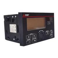
18
3 TRANSITION FROM LE-30CTN(A) TO LE7-40GU-L
3.2 Comparison of I/O Terminal Blocks
Terminal specifications
Since the terminal type changes from a screw type terminal to a spring clamp type terminal, stranded wires and bar type crimp
terminals are used for wiring. Therefore, when using a round terminal and Y terminal, terminal processing of the wiring is
necessary.
Tension control output for powder clutch/brake
After replacement from LE-30CTN(A), the same function as before replacement can be used by selecting the LE-30CT mode
in the initial setting (operation mode selection).
Control output signal
After replacement from the control output of the LE-30CTN(A), set the motor tension control output to 0 to 5 V and use it. For
LE7-40GU-L, it can also be set to output as for motor control.
Tension
detector
Input GRL Left Connect the lead wires GR=green (blue) and
WH=white of the tension detector inputs.
When only the detector on one side is used, it is
necessary to make a short circuit between GR and
WH on the other side.
The compression/tensile load is determined
automatically.
GRL Left Tension detector input
• Input range switchable
(1) -150 to +150 mV DC (LX tension detector)
resolution: Approx. 7.90 V
(2) -15 to -15 mV DC (strain gauge) resolution:
Approx. 0.790 V
When only the detector on one side is used, it is
necessary to make a short circuit between GR and
WH on the other side.
The compression/tensile load is determined
automatically.
WHL WHL
GRR Right GRR Right
WHR WHR
SG For shield connection SLD For shield connection
Analog Input AI1 Select from the following functions.
Tension setting signal, reel diameter signal,
external tension signal, taper ratio setting signal,
manual setting signal 1, manual setting signal 2,
and voltage signal of 0 to 5 V DC or 10 k
potentiometer
AI1 Selection from tension setting, stall, taper ratio,
new-reel preset, manual, tension input, and reel
• Input range switchable
(1) 0 to 5 V DC resolution: Approx. 193 V
(2) 0 to 10 V DC resolution: Approx. 193 V
• Input resistance 38 k
AI2 AI2
AI3
AIC Analog input common AIC Analog input common
Output AO1 Output for tension monitor/tension setting monitor
0 to 5 V DC Function selection by DIP switch
AO1 Selection from tension monitor, reel diameter
monitor, tension setting monitor, A-reel shaft
rotation speed output, and B-reel shaft rotation
speed output selection
• Output range switchable
(1) 0 to 5 V DC resolution: Approx. 358 V
(2) 0 to 10 V DC resolution: Approx. 358 V
• Load resistance: 1 k or more
AO2
AOC Analog output common AOC Analog output common
Contact Input RUN Operation/stop: ON=automatic operation,
OFF=stop
DI1 Selection from operation/stop, control output OFF/
ON, stall memory, inching ON/OFF, constant
tension ON/OFF, gain 1 ON/OFF, gain 2 ON/OFF,
auto/manual, reel change ON/OFF, cut torque ON/
OFF, and alarm reset ON/OFF
• Input signal voltage 24 to 28.8 V DC
• ON current about 5 mA
• Sink/source input
MI1 Select from the following functions.
Output memory, output gain 1, output gain 2,
output ON-OFF, manual output 1, and manual
output 2
DI2
MI2 DI3
MI3 DI4
DI5
DI6
MIC Contact input common 0V In sink input mode, the 0 V terminal becomes
common.
S/S In sink input mode, connect to the 24 V terminal.
Output ZT • Zero tension detection output: Set value 0 to
2000N (N, 10 N)
• Output ON with tension below the set value:
Always OFF when 0 is set.
• Relay output (250 V AC 0.5 A or 30 V DC 0.5 A)
DO1 Selection from no function, tension lower limit
detection, tension upper limit detection, tension out
of range detection, and alarm occurrence detection
• Open collector output (30 V DC, 0.1 A or less)
DO2
ZT DOC Contact output common
Item name LE-30CTN(A) LE7-40GU-L
Function Terminal Specifications Terminal Specifications
 Loading...