Learning to Use the FX Family for Positioning Control MELSEC FX PLC positioning
4 - 2
MITSUBISHI ELECTRIC
Limit switches
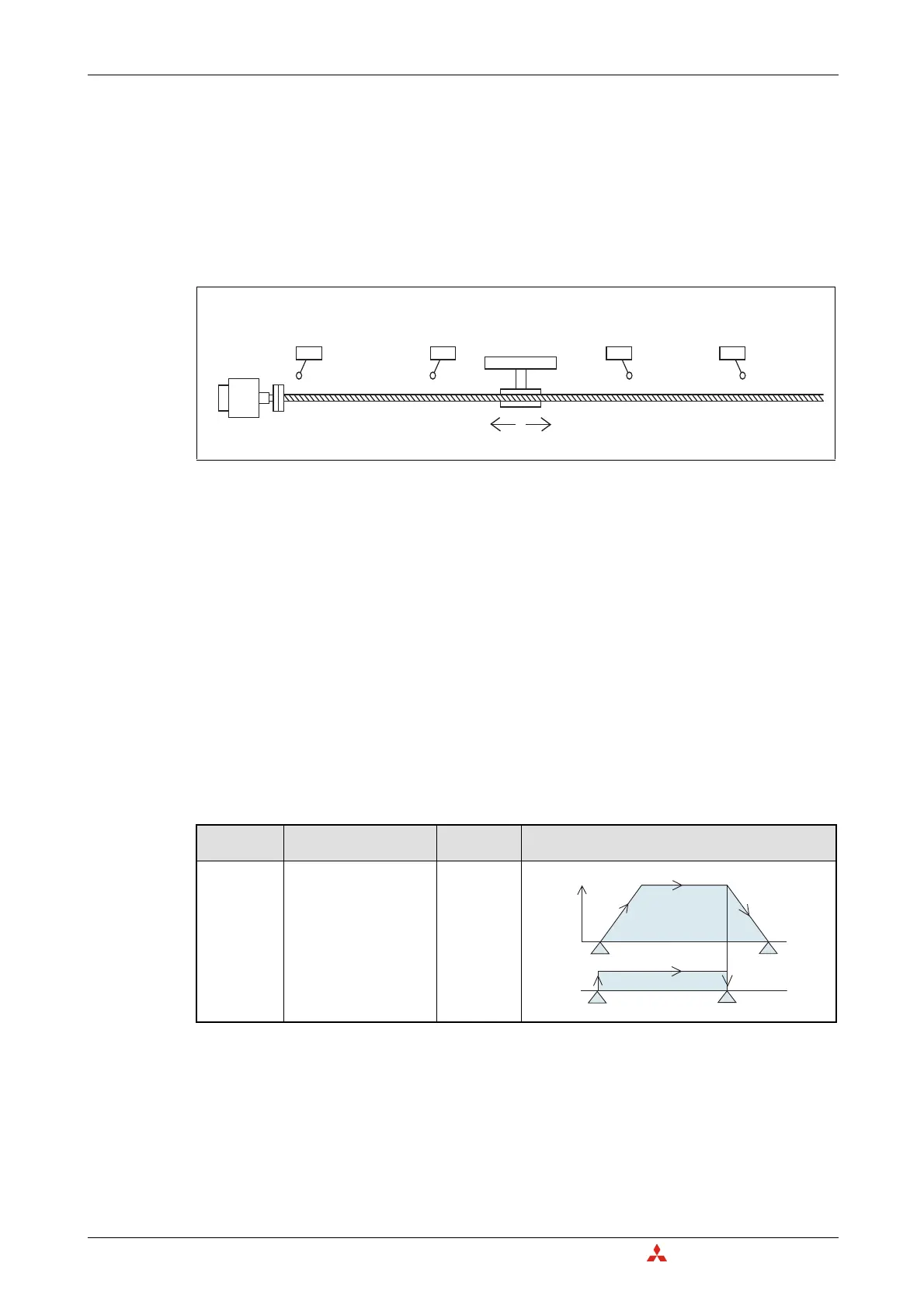
As with any other positioning system, inputs are needed to detect when the workpiece reaches the
outer boundary limits in order to prevent damage to the machine. For the FX
3G
, FX
3GC,
FX
3GE,
FX
3S
and
FX
3U(C)
programmable logic controller, limits are wired to the controller to be used with the DOG
search zero return function for reversing the motor’s direction of travel in order to hunt for the DOG
switch. These limits are called the forward rotation limit (LSF) and the reverse rotation limit (LSR).
Hardware limits are used on the servo amplifier side to stop the motor in worst case scenarios.
Sink vs. Source outputs
In general, MELSERVO Series amplifiers are configured with sink type inputs. To communicate appro-
priately with sink type inputs, sink type outputs are used on the PLC side. Therefore, when using a Mit-
subishi servo control system, a transistor sink output type PLC is used.
Options for positioning
Before choosing a PLC for a positioning system, it is important to understand the instructions avail-
able for each PLC. The FX
1S
and FX
1N
include the same set of positioning instructions. The only dis-
advantage to choosing an FX
1S
PLC for positioning is that it does not include as many I/O and that it
cannot be expanded with special function blocks for analog or communication control.
The FX
3U
, combined with high speed positioning adapters, can operate with higher pulse output fre-
quencies and includes 3 additional positioning instructions. The available instructions for FX PLCs are
described in the chart below.
141010da.eps
Fig. 4-1:
Example for limit switches
Applicable
Model
Description
Positioning
instruction
Instruction Illustration
FX
1S
FX
1N
FX
3G
FX
3GC
FX
3GE
FX
3S
FX
3U
FX
3UC
JOG operation
The motor moves in a speci-
fied direction depending
on the logic and timing of
the drive input signal.
(There is no target
position.)
DRVI
Tab. 4-2:
Instructions for FX PLCs (1)
Reverse rotation limit 2
(Servo amplifier side)
Servo motor
Reverse rotation limit 1
(Programmable
controller side)
LSR
Forward rotation limit 1
(Programmable
controller side)
LSF
Forward rotation limit 2
(Servo amplifier side)
Reverse rotation Forward rotation
Speed
JOG speed
Start
Start
JOG
command
Stop
Stop
411020da.eps

 Loading...


