Do you have a question about the Mitsubishi Electric Melservo-J3 Series MR-J3-B and is the answer not in the manual?
| Brand | Mitsubishi Electric |
|---|---|
| Model | Melservo-J3 Series MR-J3-B |
| Category | Amplifier |
| Language | English |
Instructions to avoid electrical hazards during installation, operation, and maintenance.
Guidelines to prevent fire hazards related to component placement and wiring.
Precautions to prevent physical injury from hot surfaces or moving parts.
Guidelines for safely transporting and installing the equipment.
Proper procedures and precautions for electrical wiring connections.
Steps for adjusting and testing the servo system performance.
Recommendations and precautions for operating the servo system.
Actions to take in case of faults or abnormal conditions.
Guidance on routine maintenance and component lifespan.
General operational advice and safety considerations.
Ensuring safety during product use and installation.
Information on the limited write cycles of the EEP-ROM.
Important considerations before selecting and using products.
Explanation of the purpose and requirements of EC directives.
Measures to ensure compliance with EC directives.
Details on system configuration for compliance.
Environmental conditions for proper operation and installation.
Specifications and requirements for the power supply system.
Essential grounding procedures for safety and performance.
Wiring requirements and best practices.
Information on compatible auxiliary equipment and optional items.
Guidelines for conducting Electromagnetic Compatibility (EMC) tests.
Lists compatible units and motors for UL/C-UL compliance.
Installation requirements for UL/C-UL compliance.
Information on the short-circuit current rating for safety.
Safety information regarding capacitor discharge time after power-off.
Required options and auxiliary equipment for UL/C-UL compliance.
Guidelines for attaching the servo motor for compliance.
Protection measures for wiring to ensure compliance.
Introduction to the MELSERVO-J3 series AC servo.
Diagram illustrating the functional blocks of the servo system.
Detailed standard specifications for servo amplifiers.
List of available functions with brief explanations.
Explanation of the model code structure for identification.
Table showing compatible servo amplifier and servo motor combinations.
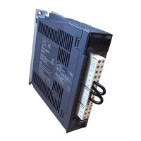
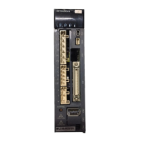
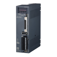
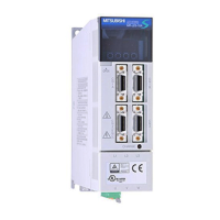
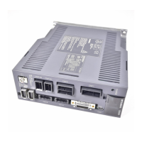
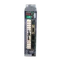
Identification of major parts and components of the servo amplifier.
System configuration diagrams with auxiliary equipment.
Requirements for proper installation direction and spacing.
Measures to prevent entry of contaminants into the unit.
Guidelines for managing cable stress and preventing damage.
Specific instructions for routing SSCNET optical fiber cables.
Periodic checks recommended for maintenance and safety.
Identification of components with limited service lives requiring replacement.
Wiring diagrams for connecting the main and control circuit power supplies.
Illustrative examples of I/O signal connections.
Detailed explanation of the power supply system and terminal functions.
Pin assignments and layouts for various connectors.
Detailed explanations of individual signals and their functions.
Timing diagrams illustrating alarm conditions and system responses.
Internal connection diagrams and descriptions of interfaces.
Proper handling of shielded cable external conductors for noise reduction.
Procedures for connecting SSCNET communication cables.
Essential instructions for connecting the servo amplifier and motor.
Specific wiring and safety precautions for motors with electromagnetic brakes.
Critical grounding procedures for safety and noise reduction.
Setting the control axis number using the rotary switch.
Procedures for powering up the system for the first time.
Steps for initiating system operation and verifying basic functions.
Understanding the servo amplifier's display indications for status and errors.
Procedures for performing test operations to verify machine and motor functions.
Modes and procedures for testing servo operation without a machine.
Performing operations without connecting the servo motor for controller checks.
Essential parameters for initial system setup and basic operation.
Parameters for adjusting servo gains and filter settings for optimal performance.
Parameters for extended functions like analog monitor and I/O settings.
Parameters for configuring digital and analog I/O signals.
Explanation of various gain adjustment techniques available.
Procedures and modes for automatic servo gain adjustment.
Step-by-step guide for manual gain adjustment.
Gain adjustment for multi-axis interpolation operations.
Comparison of auto tuning features between J2 and J3 series.
Diagram illustrating special adjustment functions.
Function for automatic detection and suppression of mechanical vibration.
Filter for reducing mechanical system resonance and vibration.
Control for further suppressing machine and workpiece vibration.
Filter to prevent high-frequency resonance during servo system response increase.
Function to change servo gains dynamically based on operating conditions.
Comprehensive list of alarms and warnings with display codes.
Detailed steps to resolve specific alarm conditions.
Actions to take when system warnings occur.
Physical dimensions and mounting information for servo amplifiers.
Outline drawings for common connector types used.
Graphs showing electronic thermal relay protection curves.
Data on power supply capacity and heat dissipation requirements.
Dynamic brake performance characteristics.
Graphs illustrating expected cable flexing life.
Data on inrush currents during power-on for various models.
Lists available cables and connector sets for system integration.
Details on regenerative options for energy recovery.
Information on the FR-BU2-(H) brake unit and its usage.
Details on the power regeneration converter for energy recovery.
Information on the common power regeneration converter.
Use and connection of external dynamic brakes for stopping.
Details on the recommended junction terminal block for wiring.
Software for parameter setting, monitoring, and testing.
Information about the battery for absolute position detection.
Attachment for external heat sink mounting.
Recommended wire specifications for various connections.
Selection of protective devices and contactors.
Use and installation of DC reactors for power factor improvement.
Use of AC reactors for power factor improvement.
Recommended relays for interface connections.
Surge absorbers for protecting equipment from voltage spikes.
Methods for minimizing electrical noise and interference.
Selection and use of leakage current breakers for safety.
EMC filters for compliance with electromagnetic compatibility standards.
Key features of the absolute position detection system.
Technical specifications for the absolute position detection system.
Steps for installing the battery for position data backup.
How to verify absolute position data using MR Configurator.
Overview of functions and menus for large capacity units.
Block diagram of the large capacity servo amplifier system.
List of items included with converter units, drive units, and motors.
Standard specifications for converter units.
Definition of model codes for converter and drive units.
Compatible combinations of system components.
Identification of parts on the converter unit.
Procedures for removing and reinstalling terminal block covers.
Wiring diagrams for servo systems with auxiliary equipment.
General installation guidelines for large capacity units.
Requirements for correct installation orientation and spacing.
Periodic inspection checks for converter and drive units.
Wiring and signal information for large capacity units.
Connection and control of the magnetic contactor.
Wiring details for the input power supply circuit.
Terminal assignments for converter and drive units.
Instructions for using connection bars between units.
Connector pin configurations for converter units.
Explanation of signals and devices for converter units.
Timing charts for power-on, alarm, and forced stop sequences.
Details of servo motor terminals and connectors.
Operation and display functions of the converter unit.
Flowchart illustrating the converter unit display sequence.
How to display and interpret various operating statuses.
Mode for diagnosing system status and I/O signals.
How to display and interpret current alarms and history.
Procedure for accessing and setting parameters.
List of parameters specific to the converter unit.
Detailed list of converter unit parameters.
Explanations and settings for specific converter unit parameters.
Troubleshooting guide for converter and drive units.
Alarms and warnings specific to the converter unit.
Alarms and warnings specific to the drive unit.
Physical dimensions and mounting information for large capacity units.
Outline dimensions for the MR-J3-CR55K(4) converter unit.
Outline dimensions for MR-J3-DU30KB4/37KB4 drive units.
Performance characteristics of large capacity servo amplifiers.
Graphs illustrating overload protection curves.
Power supply capacity and heat generation data.
Dynamic brake performance characteristics.
Data on inrush currents for large capacity units.
Information on available optional accessories for large capacity units.
Details on cables and connectors for large capacity units.
Selection and combination of regenerative options.
Selection and connection of external dynamic brakes for stopping.
Recommended wire specifications for large capacity units.
Selection of protective devices for large capacity units.
Use and installation of DC reactors for large capacity units.
Line noise filters for large capacity units.
Selection and use of leakage current breakers.
EMC filters for large capacity units.
Information on the FR-BU2-(H) brake unit for large capacity systems.
Comprehensive list of servo amplifier parameters.
List of basic and gain/filter parameters for servo amplifiers.
List of parameters for converter units.
Blank paper for recording signal layouts.
Outline drawing of a twin type connector.
Information on connector set changes to RoHS compatible products.