Do you have a question about the Mitsubishi Electric MELSERVO-J2 Series and is the answer not in the manual?
| Position Control | Yes |
|---|---|
| Speed Control | Yes |
| Torque Control | Yes |
| Series | MELSERVO-J2 |
| Type | Amplifier |
| Output Current | Varies depending on model |
| Rated Output | Varies by model (e.g., 0.1kW to 15kW) |
| Feedback System | Incremental Encoder |
| Cooling Method | Natural Cooling or Forced Air Cooling (varies by model) |
| Ambient Temperature | 0 to 55°C |
| Storage Temperature | -20 to 65°C |
| Vibration Resistance | 5.9 m/s² (0.6G) at 10-55 Hz |
| Weight | Varies depending on model |
Essential guidelines for safe operation and handling of the servo amplifier.
Crucial precautions to avoid electric shock during wiring, installation, and operation.
Key safety measures to prevent fire hazards related to the servo amplifier.
Safety instructions to prevent personal injury from mechanical or electrical hazards.
Guidelines for the proper transportation and installation of the servo equipment.
Detailed instructions for correct and secure electrical wiring of the servo system.
Procedures for adjusting the system during the test run phase.
Guidelines for the proper and safe usage of the servo amplifier.
Recommended actions for hazardous conditions or product faults.
Procedures for periodic maintenance, inspection, and replacement of servo amplifier parts.
General operational advice and information regarding equipment illustrations and usage.
Explanation of EC Directives for product standardization.
Precautions for ensuring compliance with EC Directives.
Lists compatible servo amplifiers and motors for UL/C-UL standards.
Installation requirements for UL/C-UL standard compliance.
Details conformance to short circuit rating tests.
Safety information on capacitor discharge time after power-off.
Lists UL/C-UL conforming options and auxiliary equipment.
Refers to Servo Motor Manual for motor attachment details.
Wiring protection requirements for US and Canada installations.
Overview of the MR-J2-C AC servo amplifier's functions and positioning capabilities.
A comprehensive list of all functions available in the MELSERVO-J2-C servo amplifier.
Explanation of the model name structure for servo amplifiers and motors.
Details on compatible servo amplifier and servo motor combinations.
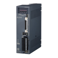
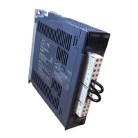
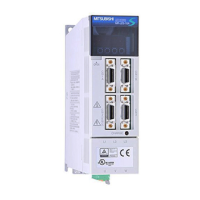
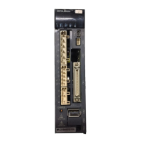
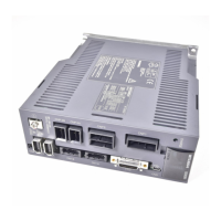
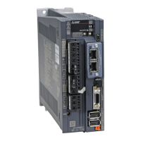
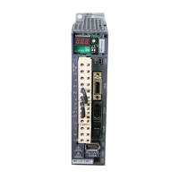
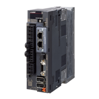
Identification and description of the main parts of the servo amplifier.
Diagram and explanation of the servo system with auxiliary equipment.
Specifies the required environmental conditions for operating the servo amplifier.
Guidelines for correct installation direction and required clearances for ventilation.
Instructions to prevent foreign materials from entering the servo amplifier.
Considerations for managing cable stress and flexing life.
A typical wiring diagram for the servo system connection.
Explanation of power supply and common line configurations.
Information on input and output signals for servo amplifier control.
In-depth explanations of specific control signals like start, stop, and limits.
Timing sequence illustration for alarm occurrences.
Details on digital input and output interfaces for external connections.
Diagrams and explanations for input power supply circuit connections.
Instructions for correctly connecting the servo amplifier to the servo motor.
Specific wiring and operation details for servo motors with electromagnetic brakes.
Essential grounding procedures for safety and noise reduction.
Instructions for wiring the control circuit terminal block (TE2).
Guidelines for fabricating and connecting cables using 3M connectors.
Pre-operation checks and procedures for initial power-on.
Explanation of automatic operation modes and command systems.
Basic definition of automatic operation mode.
Details on using the absolute value command system for positioning.
Details on using the incremental value command system for positioning.
Timing chart illustrating automatic operation sequences.
Explanation of varied speed and continuous positioning operations.
Modes for manual control like jog and pulse generator operation.
Procedures for manual jog operation of the servo motor.
Instructions for operating the servo motor using a manual pulse generator.
Various methods for performing manual home position return.
Information on configuring and using the absolute position detection system.
Using RS-422 or RS-232C for servo amplifier operation and parameter settings.
A list of all available parameters for the servo amplifier.
Controls write access to parameters, especially expansion parameters.
Detailed lists of basic and expansion parameters.
In-depth explanations of specific parameters.
Explanation and calculation of the electronic gear function.
System requirements and specifications for the servo configuration software.
Required components and configuration diagrams for using the software.
Procedure for setting the station number for communication.
Operations for reading, writing, and managing parameters using the software.
Operations for managing point table data using the software.
Assigning functions to servo amplifier I/O pins using the software.
Modes for testing servo motor operation without a machine.
Viewing and clearing the servo amplifier's alarm history.
Explanation of gain adjustment and its importance in servo systems.
Detailed procedures for adjusting servo gain parameters.
Lists parameters relevant to servo gain adjustment.
Block diagram of the servo amplifier's control section.
Explanation of the auto tuning process for servo gain.
Procedures and guidelines for adjusting gain using the auto tuning function.
Steps for performing gain adjustment via auto tuning.
Conditions required for successful auto tuning.
Methods for manually adjusting servo gain when auto tuning is insufficient.
Function to reduce servo vibration at stop, especially with low inertia ratios.
Common faults encountered during initial startup and their solutions.
Procedures for handling alarms and warnings displayed by the servo amplifier.
A list of all alarms and warnings with their display codes and definitions.
Specific troubleshooting steps and actions for each type of alarm.
Actions to take when specific warnings are displayed by the servo amplifier.
Detailed technical specifications for the MR-J2-C servo amplifier series.
Dimensional drawings for servo amplifier models and connectors.
Outline dimension drawings for MR-J2-10C to MR-J2-350C servo amplifiers.
Drawings and specifications for servo amplifier connectors.
Electronic thermal relay protection curves for servo motors and amplifiers.
Data on power supply capacity and heat generation for servo amplifiers.
Information on the dynamic brake operation and coasting distance calculation.
Graph showing calculated flexing life of encoder cables.
Overview of available optional equipment for the servo system.
Details on regenerative brake options, combinations, and selection.
Information on various cables and connectors for system setup.
Details on the junction terminal block and its usage.
Information on the maintenance junction card for PC and monitor use.
Specifications and connection for the external digital display unit.
Specifications and connection for the manual pulse generator.
Information on batteries used for absolute position detection systems.
Overview of recommended auxiliary equipment.
Recommended wire specifications for power supply and motor connections.
Recommended specifications for breakers, fuses, and contactors.
Information on power factor improving reactors and their connection.
Recommended relays for use with interfaces.
Recommended surge absorbers for electromagnetic brakes.
Techniques for reducing electrical noise in the servo system.
Method for selecting and installing leakage current breakers.
Recommended EMC filters for compliance with EN standards.
Variable resistors available for analog input settings.