Do you have a question about the Mitsubishi Electric MELSERVO-J4 MR-J4-TM and is the answer not in the manual?
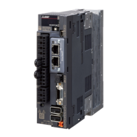
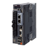
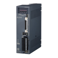
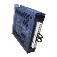
| Series | MELSERVO-J4 |
|---|---|
| Model | MR-J4-TM |
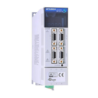
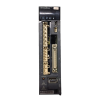
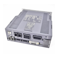
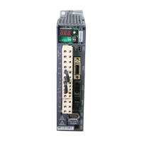
| Type | Servo Amplifier |
| Control Method | Speed, Torque, Position Control |
| Input Voltage | 3-phase 200 to 230 V AC |
| Supply Voltage | 3-phase 200V to 230V AC |
| Rated Output | 0.1kW to 7kW |
| Output Current | Varies by model |
| Communication | EtherCAT |
| Feedback System | Absolute/Incremental Encoder |
| Safety Features | STO (Safe Torque Off), SS1 (Safe Stop 1), SS2 (Safe Stop 2) |
| Protection Functions | Overcurrent, Overvoltage, Overload, Overheat, Encoder Error |
| Ambient Temperature | 0 to 55°C |
| Ambient Humidity | 90% RH or less (non-condensing) |
| Vibration Resistance | 5.9 m/s² (0.6 G) |
| Storage Temperature | -20 to 65°C |
Explains WARNING, CAUTION levels and diagrammatic symbols.
Notes to prevent electric shock during wiring and operation.
Notes to prevent fire during installation and operation.
Notes to prevent injury from incorrect voltage or wiring.
Precautions for safe transportation and installation of the equipment.
Guidelines for correct and secure wiring.
Precautions before performing test runs and adjustments.
General precautions for using the servo amplifier.
Precautions to take during corrective actions.
Precautions for maintenance, inspection, and replacement.
Waste disposal, EEP-ROM life, STO function, and standards compliance.
Lists other necessary manuals for servo usage.
Provides SI to U.S. customary unit conversion table.
Introduction to PROFINET and supported control modes.
Lists relevant document versions for PROFINET standards.
Explains terms used in PROFINET communication.
Details on physical layer, connectors, and cables.
Steps for PROFINET startup, including connection and IP settings.
Steps to safely disconnect the network.
Introduction to the object dictionary structure.
Technical specifications of the PROFINET network module.
Identifies the components of the PROFINET network module.
Explains the meaning of Network, Module, and Link/Activity LEDs.
Guidelines for connecting Ethernet cables.
Details of Standard Telegram 1, 100, and 102 for cyclic data.
Formats for request and response in acyclic data exchange.
Lists error numbers for acyclic communication.
Lists PROFIdrive-specific parameters.
Details on operating mode, fault counter, and fault numbers.
Parameters for identifying drive units and profiles.
Identification of drive objects and parameter database handling.
Information for device identification and maintenance.
Diagram and table illustrating basic state transitions.
Detailed table of state transitions based on events.
Corresponds command bit settings to state transitions.
Diagram and table of FSA state transitions.
Detailed table of FSA state transitions.
Corresponds command bits to FSA state transitions.
Format of Controlword/Statusword for different telegrams.
Definition of Control word 1 bits (PROFIdrive).
Bit definitions for CiA 402 compliant Controlword.
Bit definitions for Control DI1.
Bit definitions for Control DI2 and DI3.
Definition of Status word 1 bits (PROFIdrive).
Bit definitions for CiA 402 compliant Statusword.
Definition of Status DO 1 bits.
Definition of Status DO 2 bits.
Definition of Status DO 3 and DO 5 bits.
Specifies how to select the control mode.
Procedure for switching between control modes.
Functions and parameters for profile position mode.
Lists parameters related to profile position mode.
OMS bit details for Controlword in pp mode.
OMS bit details for Statusword in pp mode.
Feed constant parameter and set-point update process.
Explains how to set multiple set-points.
Functions and parameters for profile velocity mode.
Lists parameters related to profile velocity mode.
Controlword bit definitions for profile velocity mode.
OMS bit details for Controlword in pv mode.
Statusword bit definitions for profile velocity mode.
OMS bit details for Statusword in pv mode.
Speed setpoint and feed constant parameters.
Illustrates the operation sequence for profile velocity mode.
Functions and parameters for profile torque mode.
Lists parameters related to profile torque mode.
OMS bit details for Controlword in tq mode.
OMS bit details for Statusword in tq mode.
Feed constant parameter and tq mode operation sequence.
Functions and parameters for homing mode.
Lists parameters related to homing mode.
OMS bit details for Controlword in hm mode.
OMS bit details for Statusword in hm mode.
Table listing supported homing methods.
Provides descriptions for various homing methods.
Explains CiA 402-type homing methods.
Details specific CiA 402 home position return types.
Describes homing methods using home switch and index pulse.
Describes homing methods without index pulse.
Describes homing methods using index pulse.
Describes homing using the current position.
Provides operation examples for CiA 402-type homing.
Illustrates operation for homing methods 3 and 5.
Illustrates operation for homing methods 4 and 6.
Illustrates operation for homing methods 7 and 11.
Illustrates operation for homing methods 8 and 12.
Illustrates operation for homing methods 19 and 21.
Illustrates operation for homing methods 20 and 22.
Illustrates operation for homing methods 23 and 27.
Illustrates operation for homing methods 24 and 28.
Illustrates operation for homing methods 33 and 34.
Illustrates operation for homing methods 35 and 37.
Operation example for dog type home position return.
Operation example for count type home position return.
Operation example for data set type home position return.
Operation example for stopper type home position return.
Operation example for dog type rear end reference homing.
Operation example for count type front end reference homing.
Operation example for dog cradle type home position return.
Operation example for dog type last Z-phase reference homing.
Operation example for dog type front end reference homing.
Operation example for dogless Z-phase reference homing.
Using web browser for settings and monitoring.
Parameters for monitoring drive status.
Procedures for handling stroke end detection.
Setting upper and lower software limits for position.
Setting positive and negative torque limits.
Setting motor rotation direction for commands.
Using the touch probe for position latching.
Detailed settings and status for touch probe function.
Timing chart illustrating touch probe operation.
Using the high-precision touch probe feature.
Using the one-touch tuning function for automatic tuning.
Procedure for performing one-touch tuning via network.
Function to check amplifier life for maintenance.
Estimating friction and vibration for machine health.
Decelerating the motor to a stop using quick stop.
Decelerating the motor to a stop using the Halt function.
Decelerating the motor to a stop using Ramp Stop.
Definitions of parameters related to alarms.
Changing and storing servo amplifier parameters.
Procedures for enabling parameters.
Positioning using module coordinates (degrees).
Differences when degree unit is selected.
Operation patterns for degree setting.
Saving parameters to EEP-ROM using Store Parameters.
Comprehensive list of manufacturer-specific PROFIdrive parameters.
Categorization of objects into Monitor, Control, and PDS.
Objects grouped by control function (Position, Velocity, Torque, Homing, etc.).
Objects related to alarm history and current alarms.
Current alarm, parameter error numbers, and error list.
Introduction to various monitor objects.
Regenerative load, effective load, peak load, instantaneous torque, one-revolution position, ABS counter.
Load inertia, bus voltage, load-side feedback and droop pulses, encoder info.
Load-side encoder info, motor thermistor temp, motor feedback, electrical angle, position deviation.
Motor speed deviation, encoder temp, settling time, oscillation frequency, tough drive ops.
Power consumption, alarm monitors for feedback, speed, droop pulses.
Alarm monitors for command pulses, frequency, load ratios.
Alarm monitors for torque, position, ABS counter, inertia ratio, bus voltage.
Alarm monitors for load-side feedback/droop pulses, encoder info, motor temp.
Alarm monitors for motor feedback, electrical angle, position/speed deviation, encoder temp.
Alarm monitors for settling time, oscillation frequency, drive operations, power consumption.
Objects for machine diagnostics and friction torque.
Current status of machine diagnostics.
Friction torque and vibration level monitoring during stop.
Vibration frequency/level during motor operation.
Control commands for Digital Inputs 1, 2, and 3.
Status of Digital Outputs 1, 2, 3, and 5.
Setting the speed limit value for torque mode.
Motor rated speed, device name, hardware/software versions, serial number.
User parameter configuration and encoder status.
Setting the mode for one-touch tuning.
Status, stop command, clear, and error codes for one-touch tuning.
PDS control objects including error codes and control/status words.
Halt option, modes of operation, and supported drive modes.
Objects for position control functions.
Position actual values and following error window/timeout.
Position window settings and positioning option code.
Following error value, control effort, and velocity demand/actual values.
Objects specific to profile velocity mode.
Velocity window, window time, threshold, and threshold time settings.
Setting the target velocity for profile velocity mode.
Objects specific to profile torque mode.
Target torque, max torque, torque demand, and actual torque.
Torque slope, profile type, and positive/negative torque limits.
Objects specific to profile position mode.
Target position and position range limit settings.
Max profile velocity, max motor speed, profile velocity, and acceleration.
Profile deceleration, quick stop deceleration, and motion profile type.
Objects related to homing mode.
Home offset, homing method, and homing speeds parameters.
Lists all supported homing methods with their numbers.
Objects related to factor groups.
Polarity setting and position encoder resolution.
Gear ratio and feed constant settings.
SI unit position and velocity settings.
Optional application FE objects, including digital inputs.
Objects related to the touch probe function.
Details of touch probe status and position values.