Do you have a question about the Mitsubishi Electric Melservo-J4 MR-J4-_TM Series and is the answer not in the manual?
| Manufacturer | Mitsubishi Electric |
|---|---|
| Type | Amplifier |
| Category | Amplifier |
| Compatible Motors | HG Series Servo Motors |
| Control Mode | Position, Speed, Torque Control |
| Input Power Supply | 3-phase 200 V AC to 240 V AC, 50 Hz/60 Hz |
| Communication Interface | SSCNET III/H |
| Feedback System | Absolute encoder, Incremental encoder |
| Protection Features | Overcurrent, Overvoltage, Overload, Encoder Error Protection |
Covers WARNING, CAUTION, and symbol explanations for safe operation.
Proper grounding, personnel competency, installation, and electrical connections to prevent shock.
Fire hazard prevention using proper installation, contactors, breakers, and foreign matter prevention.
Correct wiring, heat awareness, installation, transportation, and environmental conditions.
Proper handling, stacking, clearance, and environmental conditions for installation.
Secure wiring, correct component placement, and cable management for reliable connections.
Procedures for test runs, parameter settings, and safe usage.
Safety during corrective actions, maintenance, and general operation guidelines.
Procedures for waste disposal and understanding EEP-ROM write limitations.
References for STO function, global standards compliance, and relevant documentation.
Defines EtherCAT, its network module, and CiA 402 drive profile compatibility.
Explains EtherCAT states and communication statuses like Init, Pre-Op, Operational.
Details communication parameters, standards, and startup procedures.
Lists EtherCAT supported control modes (CSP, CSV, etc.) and functions.
Defines the object dictionary and its section definitions, including EEP-ROM saving.
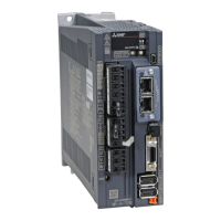
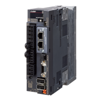
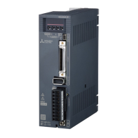
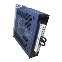
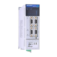
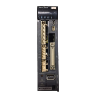
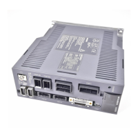
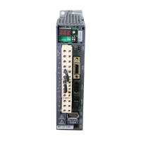
Lists module specs and identifies components like LEDs and ports.
Explains LED functions and proper Ethernet cable connection.
Explains PDO cycle application and related objects for settings.
Shows default mapping configurations for received and transmitted PDOs.
Details specifications for arranging objects in PDO data transfer.
Lists objects required for different control modes for RxPDO communication.
Lists services for SDO transfer and abort codes with causes.
Explains the internal state control based on CiA 402 drive profile states and transitions.
Details bits and objects for controlling drive functions and monitoring status.
Details how to select and switch between different control modes.
Explains various drive profile modes (CSP, CSV, TQ, PP, PV, HM) and their objects.
Explains PT, JG, and IDX modes, their objects, and operation sequences.
Explains touch probe function, related objects, and digital I/O.
Details quick stop, halt, software position limits, and torque limits.
Explains polarity settings and degree function for positioning.
Explains how to compensate torque command with offset values.
Lists objects for monitoring various parameters like pulses, speed, torque, and voltage.
Explains incremental counter usage for PDO errors and stroke end response.
Lists objects for accessing and clearing alarm history.
Defines parameter objects and the process for enabling them.
Explains obtaining position information from scale measurement encoders.
Explains the one-touch tuning feature and its network procedure.
Explains functions for estimating machine friction/vibration and diagnosing amplifier life.
Describes saving parameters and lists all supported objects by group.
Details general objects like Device Type, Error Register, versions, and parameter definitions.
Details objects for configuring Receive and Transmit PDO mappings.
Details sync manager types, RxPDO, and TxPDO assignments.
Details objects for accessing alarm history and monitoring various parameters.
Details objects for external outputs, diagnostics, and friction measurements.
Defines objects for error codes, controlword, statusword, and quick stop options.
Details objects for position control, velocity modes, torque modes, homing, and tables.
Defines objects related to gear ratio, polarity, and encoder resolution.
Details touch probe functions and digital inputs/outputs.