J
Jamie ChenSep 9, 2025
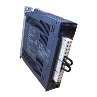
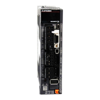
What to do if Mitsubishi Electric MR-J3-B displays servo forced stop warning?
- RRichard JohnstonSep 9, 2025
To resolve the 'Servo forced stop warning' on your Mitsubishi Electric Amplifier, make the Servo off status and interrupt the main circuit power.