K
Kylie SteeleSep 12, 2025
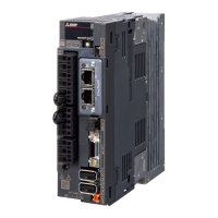
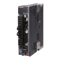
How to troubleshoot a board error on Mitsubishi Electric Servo Drives?
- TthompsonwilliamSep 12, 2025
If your Mitsubishi Electric Servo Drives are showing a board error, it indicates a fault with one of the boards. Replace the faulty board.