TECHNICAL & SERVICE MANUAL
SPLIT-TYPE, HEAT PUMP AIR CONDITIONERS
CONTENTS
1. TECHNICAL CHANGES·································2
2. SAFETY PRECAUTION··································3
3.
COMBINATION OF INDOOR AND OUTDOOR UNITS
···7
4. PART NAMES AND FUNCTIONS ··················7
5. SPECIFICATIONS···········································8
6. DATA ·····························································12
7. OUTLINES AND DIMENSIONS····················14
8. WIRING DIAGRAM·······································17
9. WIRING SPECIFICATIONS ··························20
10.
REFRIGERANT SYSTEM DIAGRAM
··············22
11. TROUBLESHOOTING···································28
12. DISASSEMBLY PROCEDURE ·····················81
13. PARTS LIST ················································108
14. OPTIONAL PARTS························Back Cover
No.OC294
REVISED-EDITION-D
R410A
2004
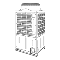
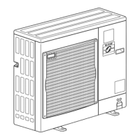
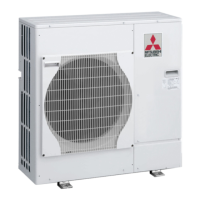
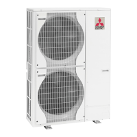
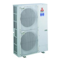
Outdoor unit
[model names]
PUHZ-RP1.6VHA
PUHZ-RP2VHA
PUHZ-RP2.5VHA
PUHZ-RP3VHA
PUHZ-RP4VHA
PUHZ-RP5VHA
PUHZ-RP6VHA
PUHZ-RP4YHA
PUHZ-RP5YHA
PUHZ-RP6YHA
[Service Ref.]
PUHZ-RP1.6VHA
PUHZ-RP2VHA
PUHZ-RP2.5VHA
PUHZ-RP2.5VHA
1
PUHZ-RP3VHA
PUHZ-RP3VHA
1
PUHZ-RP4VHA
PUHZ-RP4VHA
1
PUHZ-RP5VHA
PUHZ-RP5VHA
1
PUHZ-RP6VHA
PUHZ-RP6VHA
1
PUHZ-RP4YHA
PUHZ-RP5YHA
PUHZ-RP6YHA
Revision:
• PUHZ-RP4YHA,
PUHZ-RP5YHA,
PUHZ-RP6YHA are added in
REVISED EDITION-D.
• Some descriptions have
been modified.
• Please void OC294 REVISED
EDITION-C.
Model name
indication
PUHZ-RP2.5VHA
PUHZ-RP3VHA
OC294-D-1.qxp 05.3.9 11:01 AM Page 1