45
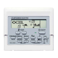
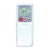
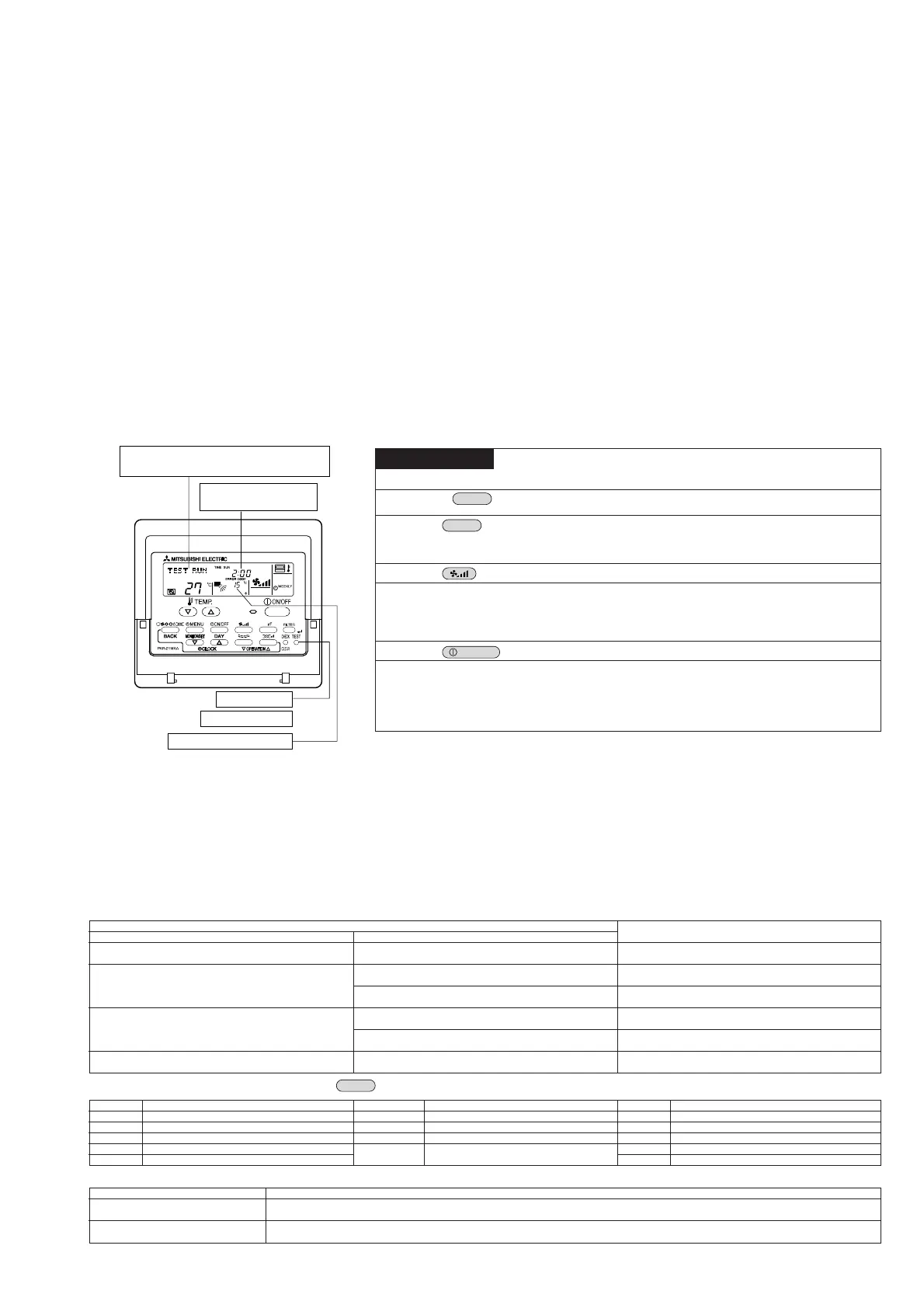
“TEST RUN” and the currently selected
operation mode are displayed alternately.
Displays the remaining
test run time.
[TEST] button
Test run indicator
Pipe (fluid) temperature
77
77
7. Test Run by the Remote Controller (for Mr. SLIM)
1. Points to be Checked before Test Run
● After installation of the indoor and outdoor units, piping work and electrical wiring work, check that there is no refrigerant leakage,
loosened connections or incorrect polarity connections.
● Measure the impedance between each power line (R, S, T) of the outdoor unit and the ground using a 500 V megger, and make
sure that it is 1.0 MΩ or more. If the indoor unit is equipped with a heater or if power is supplied to the outdoor and indoor units
separately, also check the impedance for each power line (R, S, T) of the heater unit.
* Never perform the above operation for indoor/outdoor unit connecting terminal block (S1, S2, S3) and remote controller
terminal block (1, 2). This may cause a breakdown.
● Before turning on the power, make sure that the test run switch (SW4) on the outdoor control board is set to OFF.
● To protect the compressor, the power must be turned ON 12 hours before the start of operation.
● For models that require certain functions (e.g., airflow, auto power failure recovery) to be changed, refer to “V. Function Selection
of Remote Controller” and change the settings.
● For replacement operation when using preexisting R22 refrigerant piping, refer to the outdoor unit installation manual. (Outdoor
units: MPUZ-RP112 to RP280)
2. Test Run using the Remote Controller
■ Test run method
Before starting the test run, the instruction manual must be read thoroughly. (In particular, items regarding safety must be carefully read.)
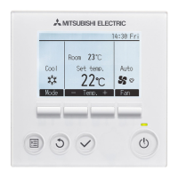
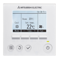
● The OFF timer (2 hours) is activated when a test run is started, and causes the test run to stop automatically after two hours have elapsed.
● The room temperature display area shows the pipe (fluid) temperature during the test run.
*1: After the power is turned ON, system setup mode will be activated and the operation lamp (green) and “PLEASE WAIT” on the
remote controller will flash. LED1 on the indoor control board will come ON, LED2 will either come ON (if the address is “0”) or
remain OFF (if the address is not “0”), and LED3 will flash.
Both LED1 (green) and LED2 (red) on the outdoor control board will come ON. (LED2 (red) goes OFF at the end of system setup mode.)
If the LEDs on the outdoor control board are digital, [- ] and [ -] will be displayed alternately at 1-second intervals.
● If you are unable to complete any of the above test run operation procedures, it may be due to the following causes, so remove the cause.
(The following symptoms may be observed during test run mode. The “startup” display listed in the table is described above in *1.)
Operating Procedure
1. Turn ON the main power.
2. Press the
button
twice.
3. Press the
button.
4. Press the
button.
5. Check that the outdoor unit’s
fan is rotating.
6. Press the
button to stop the test run.
7. Register the contact number.
It is not possible to operate the remote controller if “PLEASE WAIT” is displayed in the
room temperature display area. Wait until “PLEASE WAIT” disappears. “PLEASE WAIT”
remains displayed for approximately two minutes after the power is turned ON. *1
“TEST RUN” and the name of the currently selected operation mode are displayed
alternately.
Cool mode .... Check that cold air is blown out.
Heat mode .... Check that warm air is blown out. (It takes a while before warm air
starts to blow out.)
Fan/dry operation cannot be performed.
Check that the auto vane moves.
The outdoor unit controls the performance of the air conditioner by controlling the
fan rotating speed. The fan rotates at low speeds depending on the condition of the
outside air, and it will not increase speed unless performance is insufficient.
This may cause the fan to stop or rotate in reverse direction due to external wind,
but this is not a malfunction.
Register the telephone number to be contacted when an error occurs (for this procedure,
refer to “4.3.3 Contact Number Setting for Error Situation”). With PAR-21MAA, the
telephone number (maintenance company or distribution outlet) to be contacted when
an error occurs can be registered in the remote controller. Once it is registered, it will
appear when an error occurs. For the registration method, refer to the installation
manual supplied with the remote controller or the outdoor unit’s instruction manual.
Symptoms
Remote Controller Display
Remote controller is displaying “PLEASE WAIT” and opera-
tion is not possible.
After power is turned ON, “PLEASE WAIT” is displayed for
approximately three minutes, and then an error code is dis-
played.
No display messages appear even when the remote control-
ler’s operation switch is turned ON (operation lamp does not
light up).
Operation display appears when remote controller operations
are executed, but soon disappears.
Outdoor Control Board LEDs (< > for digital display)
After the “startup” display, only the green LED lights up. < 00 >
After the “startup” display, the green LED (once) and red LED
(once) flash alternately. <F1>
After the “startup” display, the green LED (once) and red LED
(twice) flash alternately. <F3, F5, F9>
After the “startup” display, the green LED (twice) and red LED
(once) flash alternately. <EA, Eb>
After the “startup” display, only the green LED lights up. < 00 >
After the “startup” display, only the green LED lights up. < 00 >
Cause
• After power is turned ON, system startup lasts for about two minutes,
during which “PLEASE WAIT” is displayed (correct operation).
•
Incorrect outdoor terminal block connections (R, S, T and S1,
S2, S3)
•
Outdoor unit protective device connector is open.
•
Incorrect wiring between the indoor and outdoor units (Incorrect polarity connection for S1, S2, S3)
•
Remote controller transmission wire is short-circuited.
•
There is no outdoor unit for address “0” (an address other than “0” is set).
•
Wire-breakage of remote controller transmission cable
•
After cancellation of function selection, operation is not possi-
ble for about 30 seconds (correct operation).
* Self-diagnosis can be performed by pressing the
button on the remote controller twice. For an explanation of the error codes, refer to the table given below.
LCD
P1
P2
P4
P5
P6
Error description
Intake air sensor error
Pipe (fluid) sensor error
Drain sensor error
Drain overflow protection activated
Anti-freeze/overheat protection activated
LCD
P8
P9
Fb
U* to F*
(*: Alphanumeric, except for Fb)
Error description
Abnormal pipe temperature
Pipe (fluid) sensor error
Indoor control board error
Outdoor unit error
(Check the electric wiring of the affected unit.)
LCD
E0 to E5
E6 to E F
— — — —
F F F F
Error description
Signal transmission error between remote controller and indoor unit
Signal transmission error between indoor and outdoor units
No error code history
No corresponding unit
For details of the LEDs (LED1, 2, 3) on the indoor control unit, see the table below.
LED 1 (microcomputer power supply) Indicates whether power is supplied to the control board. Make sure that the LED is always lit.
LED 2 (power to remote controller) Indicates whether power is supplied to the wired remote controller. Only the LED located on the indoor units that are connected to the outdoor unit
(address “0”) will be lit.
LED 3 (signal transmission between Indicates presence of signal transmission between the indoor and outdoor units. Make sure that the LED is flashing.
indoor and outdoor units)
 Loading...