EasyManua.ls Logo

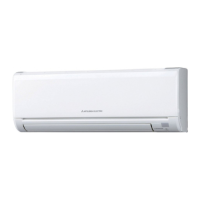
Mitsubishi Electric PKA-A18LA1 User Manual

Mitsubishi Electric PKA-A18LA1
54 pages
To Next Page IconTo Next Page
Page #1 background imageLoading...
Page #1 background image
SERVICE MANUAL
Indoor unit
[Model Name] [Service Ref.]
PKA-A12LA1
PKA-A12LA1
PKA-A18LA1
PKA-A18LA1
PARTS CATALOG (TCB117)
INDOOR UNIT
SPLIT-SYSTEM HEAT PUMP
No. TCH117
March 2023
CONTENTS
1. REFERENCE MANUAL ······················2
2. SAFETY PRECAUTION ······················2
3. PARTS NAMES AND FUNCTIONS ·······5
4. SPECIFICATIONS ······························6
5. NOISE CRITERION CURVES ···············7
6. OUTLINES AND DIMENSIONS ············8
7. WIRING DIAGRAM ···························· 9
8. REFRIGERANT SYSTEM DIAGRAM··· 10
9. TROUBLESHOOTING ······················ 11
10. FUNCTION SETTING ······················· 26
11. SPECIAL FUNCTION ······················· 27
12. DISASSEMBLY PROCEDURE ··········· 30
13. REMOTE CONTROLLER ·················· 34
WIRED REMOTE CONTROLLER
(Option)
WIRELESS REMOTE
CONTROLLER
(Option)
MENU
ON
OFF
RETURN
SELECT
HOLD

Questions and Answers:

Mitsubishi Electric PKA-A18LA1 Specifications

General IconGeneral
BrandMitsubishi Electric
ModelPKA-A18LA1
CategoryAir Conditioner
LanguageEnglish

Summary

2 SAFETY PRECAUTION

2-1. ALWAYS OBSERVE FOR SAFETY

General safety rule to observe before accessing terminals; ensure power is disconnected.

2-2. CAUTIONS RELATED TO NEW REFRIGERANT

Specific safety advice for units using R410A refrigerant.

[1] Warning for service

[2] Cautions for service

4 SPECIFICATIONS

7 WIRING DIAGRAM

8 REFRIGERANT SYSTEM DIAGRAM

9 TROUBLESHOOTING

9-1. TROUBLESHOOTING

General guide on how to approach troubleshooting based on reoccurring or non-reoccurring issues.

9-2. MALFUNCTION-DIAGNOSIS METHOD BY REMOTE CONTROLLER

[Output pattern A] Errors detected by indoor unit

Lists error codes and symptoms detected by the indoor unit via remote controller.

[Output pattern B] Errors detected by unit other than indoor unit (outdoor unit, etc.)

Lists error codes and symptoms detected by units other than the indoor unit.

9-3. SELF-DIAGNOSIS ACTION TABLE

9-4. TROUBLESHOOTING OF PROBLEMS

9-5. EMERGENCY OPERATION

9-5-1. When wireless remote controller fails or its battery is exhausted

Procedure for activating emergency cooling/heating using unit buttons when the remote fails.

9-6. HOW TO CHECK THE PARTS

10 FUNCTION SETTING

13 REMOTE CONTROLLER

13-2. ERROR INFORMATION

13-3. SERVICE MENU

13-4. TEST RUN

13-5. FUNCTION SETTING

13-6. ERROR HISTORY

13-7. SELF-DIAGNOSIS

13-8. REMOTE CONTROLLER CHECK

Related product manuals