What does Error Code 6832 mean on a Mitsubishi Electric PUHY-P192 Air Conditioner?

What does Error Code 6832 mean on a Mitsubishi Electric PUHY-P192 Air Conditioner?
| Brand | Mitsubishi Electric |
|---|---|
| Model | PUHY-P192 |
| Category | Air Conditioner |
| Language | English |
Essential checks and procedures to follow before performing any service on the unit.
List of required tools and materials for installation and servicing of the unit.
Specifications and types of copper pipes suitable for refrigerant systems.
Guidelines for storing refrigerant piping to prevent contamination and moisture ingress.
Instructions on using ester oil, ether oil, or alkylbenzene for coating flares and flanges.
Procedures and precautions for brazing refrigerant piping, emphasizing cleanliness and material use.
Method for conducting air tightness tests using nitrogen, and leak detection for R410A.
Procedures for vacuum drying the refrigerant system to remove moisture and ensure proper vacuum levels.
Guidelines for charging refrigerant, emphasizing liquid phase charging for R410A and cylinder usage.
Procedures for replenishing refrigerant in case of a leak, referencing specific sections for details.
Comparison of chemical and pressure characteristics between R410A and conventional refrigerants.
Information on refrigerating machine oil used in HFC systems and effects of contaminants.
Table summarizing compatible indoor units with different types of outdoor units.
Guidelines for wiring work, including cable types, lengths, and control wiring specifications.
Procedures for setting switches and addresses for various units and controllers in the system.
Examples of typical system connections for MA and M-NET remote controllers.
Control wiring diagram and cautions for a system with an MA remote controller.
Control wiring diagram and cautions for a system with an M-NET remote controller.
Control wiring and troubleshooting for systems with both MA and M-NET remote controllers.
Allowable lengths for refrigerant piping sections and height differences between units.
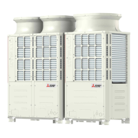
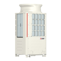
Illustrations of outdoor unit components and their refrigerant circuit diagrams.
Details of the control box, including internal components and high-voltage warnings.
Diagrams of the outdoor unit control board, INV board, and fan board with connector labels.
Comparison of functions and specifications for MA and M-NET (ME) remote controllers.
Procedures for group settings, interlock settings, and address management using the ME remote controller.
Instructions for setting up interlocks between LOSSNAY units and indoor units using the MA remote controller.
Guide to using the remote controller's built-in temperature sensor for operation control.
Detailed electrical wiring diagrams for PUHY-P72, P96, THMU-A outdoor units.
Wiring diagram illustrating the connections for the transmission booster unit.
Schematic diagrams of the refrigerant circuits for PUHY-P72, P96, and P120 outdoor units.
Description of the function and specifications of key components in the refrigerant circuit.
Details on DIP switch functions and factory settings for outdoor unit control boards.
Explanation of outdoor unit control methods, including startup sequence and bypass control.
Flowcharts illustrating indoor and outdoor unit operation modes for cooling, heating, and dry.
Checklist of essential items before performing a test run on the air conditioning unit.
Step-by-step guide for performing a test run using the MA remote controller (PAR-21MAA).
Understanding refrigerant characteristics and their impact on unit operation before adjustment.
Identifying symptoms of over/undercharging and procedures for adjusting refrigerant amount.
Detailed flowchart and procedure for adjusting refrigerant amount using the unit's adjust mode.
List of normal operating symptoms that may occur during or after operation.
Reference data tables for standard operating conditions during cooling and heating operations.
Comprehensive list of error codes, their definitions, and applicable units for troubleshooting.
Guidance on interpreting and responding to error codes displayed on the remote controller.
Methods for investigating transmission line issues, including wave shape and noise analysis.
Detailed troubleshooting steps for key components like sensors, valves, and fans.
Procedures for identifying and repairing refrigerant leaks in indoor and outdoor units.
Step-by-step guide for safely removing and replacing the compressor unit.
Guide to interpreting LED error codes displayed on the outdoor unit control board.
Explanation of the service monitor's 7-segment LED display and its interpretation.
Information displayed on the LED monitor during the unit's initial setting process.
Details on the outdoor unit's clock function, error history storage, and time display.
Table detailing the display of various operating data and error codes via SW1 settings.


