Do you have a question about the Mitsubishi Electric QS001CPU and is the answer not in the manual?
Discusses precautions for designing the system, including external circuits and protection.
Covers precautions for safely mounting and installing the safety programmable controller.
Details safe wiring practices for the programmable controller and its components.
Outlines critical steps and precautions for starting up and maintaining the system.
Highlights the new features and capabilities of the QS series CPU module.
Describes the system configuration and component layout for the safety programmable controller.
Details the configuration of peripheral devices that can be used with the system.
Lists the detailed performance specifications of the QS001CPU module.
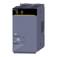
Identifies and describes the physical parts and indicators on the CPU module.
Explains the procedure for performing a reset operation on the CPU module.
Details the performance specifications for the power supply modules.
Provides precautions for connecting the system to an uninterruptible power supply (UPS).
Outlines the specifications of the base unit used for installing modules.
Details the specifications of the Q6BAT battery used for program memory backup.
Provides instructions on how to install the battery into the CPU module.
Describes the initial procedures and mode switching for operating in SAFETY MODE.
Explains precautions for conforming to the EMC Directive for system installation.
Details requirements for conforming to the Low Voltage Directive for installation and wiring.
Explains how to calculate heat generation and ambient temperature rise within the panel.
Provides instructions and precautions for installing modules onto the base unit.
Covers essential wiring precautions for the system components.
Lists daily inspection items to ensure the system operates correctly.
Details periodic inspection items for system maintenance every 6 months to 1 year.
Explains battery life and the procedure for replacing the CPU module battery.
Covers fundamental principles and steps for effective troubleshooting.
Provides flowcharts to diagnose and resolve common issues based on error indicators.
Lists error codes, their meanings, causes, and corrective actions for troubleshooting.
Details the procedure for clearing errors and resetting the system.
Lists error codes returned by the CPU module during communication with GX Developer.
Provides external dimension drawings for the CPU module, power supply, and base unit.
Lists additional functions and compatibility based on GX Developer versions.
Outlines regulations and guidelines for transporting lithium batteries.
| Model | QS001CPU |
|---|---|
| Series | Q Series |
| Input Voltage | 24V DC |
| Communication Ports | RS-232 |
| Programming Language | Ladder Logic, Instruction List |
| Operating Temperature | 0°C to 55°C |
| Humidity | 5% to 95% (non-condensing) |
| Shock Resistance | 147 m/s², 3 times in each direction (X, Y, Z) |
| Storage Temperature | -25 to 75°C |