2
SYSTEM CONFIGURATION
2.1 System Configuration
2 - 1
1
OVERVIEW
2
SYSTEM
CONFIGURATION
3
GENERAL
SPECIFICATIONS
4
CPU MODULE
5
POWER SUPPLY
MODULE
6
BASE UNIT
7
BATTERY
8
CPU MODULE START-
UP PROCEDURES
CHAPTER2 SYSTEM CONFIGURATION
This section describes the system configuration of the QS series CPU module cautions on
use of the system, and configured equipment.
2.1 System Configuration
The following figure shows the system configuration of the safety programmable controller
system when the QS series CPU module is used.
(1) System configuration when the CPU(QS001CPU) is used
* 1 : For mountable modules, refer to Section 2.1.1 "Precautions for system configuration".
Figure 2.1 System configuration
QS034B base unit
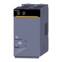
QS001CPU CPU module
Battery for a CPU
(Q6BAT)
Power supply/intelligent function module
*1
 Loading...


