10 - 22
MELSEC-A
10 ADVANCED POSITIONING CONTROL
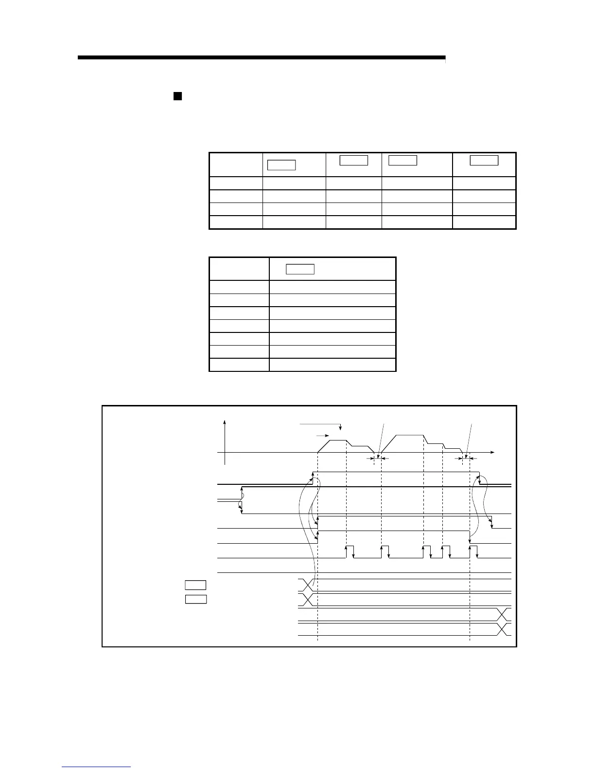
Start time chart
The following chart shows a time chart in which the positioning data 1, 2, 10, 11,
and 12 of axis 1 are continuously executed as an example.
(a) Start block data setting example
Axis 1 start
block data
Da.10
Shape
Da.11
Start data No.
Da.12
Special
start command
Da.13
Parameter
1st point 1: Continue 1 0: Normal start –
2nd point 0: End 10 0: Normal start –
•
•
(b) Positioning data setting example
Axis 1 position-
ing data No.
Da.1
Operation pattern
1 01: Continuous positioning control
2 00: Positioning complete
•
10 11: Continuous path control
11 11: Continuous path control
12 00: Positioning complete
•
(c) Start time chart
[Y10]
PLC READY signal
AD75 READY signal
[X1]
[X4]
Positioning complete signal
V
t
Error detection signal
Positioning data No.
12(00)
Operation pattern
1(11)
1st point [buffer memory address 4300]
2nd point [buffer memory address 4301]
11(11)
10(11)
2(00)
7000
1
-32767
10
(8001
H
)
(000A
H
)
Cd.11 Positioning start No.
Cd.31 Positioning starting point No.
Positioning start signal
[X0]
Start complete signal
BUSY signal
[XA]
[X7]
[Y1D]
Dwell time Dwell time
Fig. 10.3 Start time chart for advanced positioning control (block start)
 Loading...


