3 - 17
MELSEC-A
3 SPECIFICATIONS AND FUNCTIONS
3.5.3 List of input signal details
The details of each AD75 external device connection connector (for 1 axis) signal are
shown below.
Signal name Pin No. Signal details
Common
36
35
•
Common for near-point dog signal, upper/lower limit, stop signal,
speed/position changeover signal, and external start signal.
Manual pulse generator
(B phase –)
Manual pulse generator
(A phase –)
28
27
Manual pulse generator
(B phase +)
Manual pulse generator
(A phase +)
10
9
•
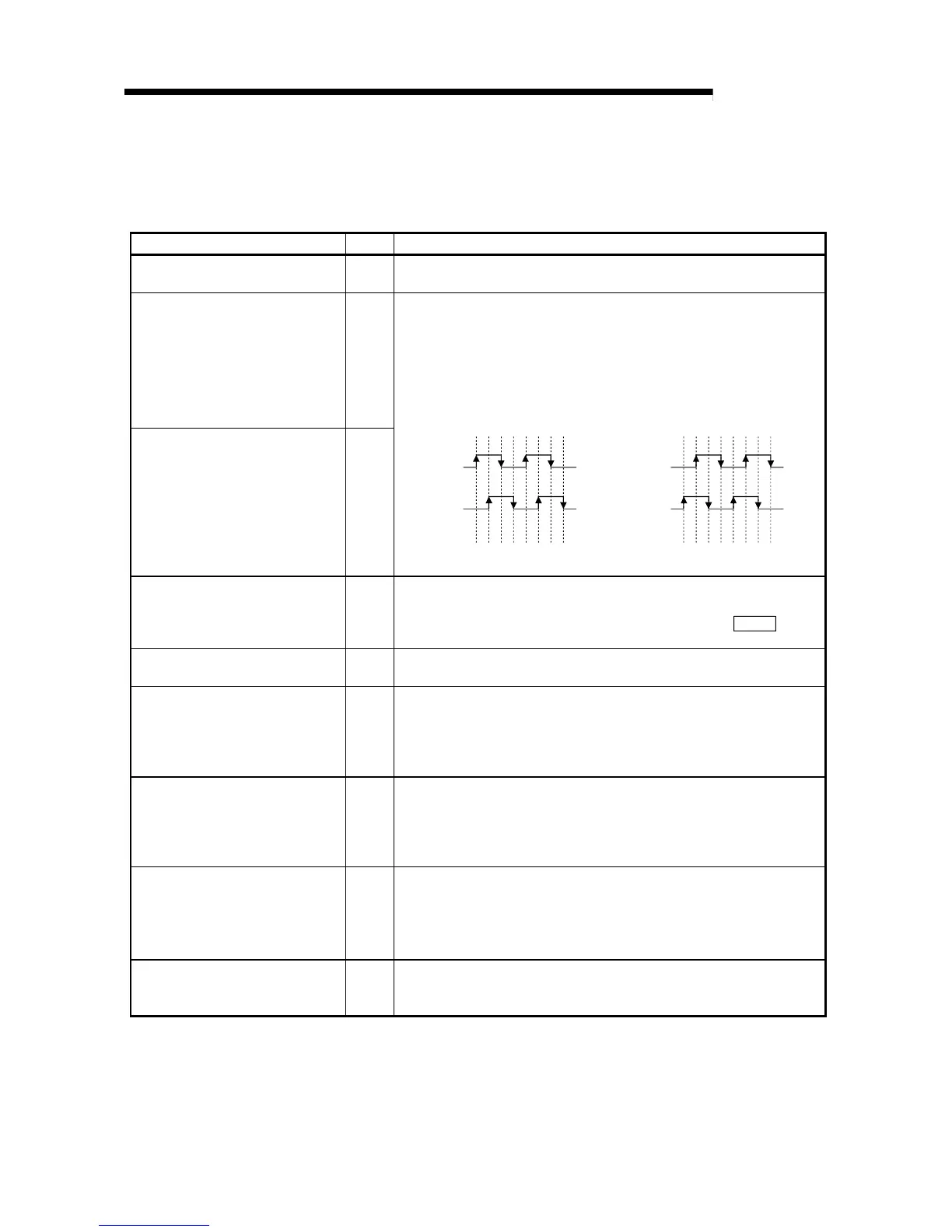
Input the pulse signal from the manual pulse generator A phase and B
phase.
•
If the A phase is advanced more than the B phase, the positioning
address will increase at the rising edge and falling edge of each phase.
•
If the B phase is advanced more than the A phase, the positioning
address will decrease at the rising edge and falling edge of each phase.
[When increased] [When decreased]
+1+1+1+1+1+1+1+1 -1 -1 -1 -1 -1 -1 -1 -1
A phase
B phase
Positioning
address
A phase
B phase
Positioning
address
External start signal 16
•
Use as the positioning start, speed change request and skip request
input signal from an external source.
•
Set which function to use the external start signal with in "
Pr.43
External start function selection".
Speed/position changeover signal 15
•
Input the control changeover signal for the speed/position changeover
control.
Stop signal 14
•
Input when positioning is stopped.
•
When this signal turns ON, the AD75 will stop the positioning being
executed.
After that, even if this signal turns from ON for OFF, the system will not
start.
Lower limit signal 13
•
This signal is input from the limit switch installed at the stroke lower limit
position.
•
Positioning will stop when this signal turns OFF.
•
When zero point return retry function is valid, this will be the lower limit
for finding the near-point dog signal.
Upper limit signal 12
•
This signal is input from the limit switch installed at the stroke upper limit
position.
•
Positioning will stop when this signal turns OFF.
•
When zero point return retry function is valid, this will be the upper limit
for finding the near-point dog signal.
Near-point dog signal 11
•
Use this for detecting the near-point dog during machine zero point
return.
•
The near-point dog signal is detected at turning from OFF to ON.
 Loading...


