3 - 18
MELSEC-A
3 SPECIFICATIONS AND FUNCTIONS
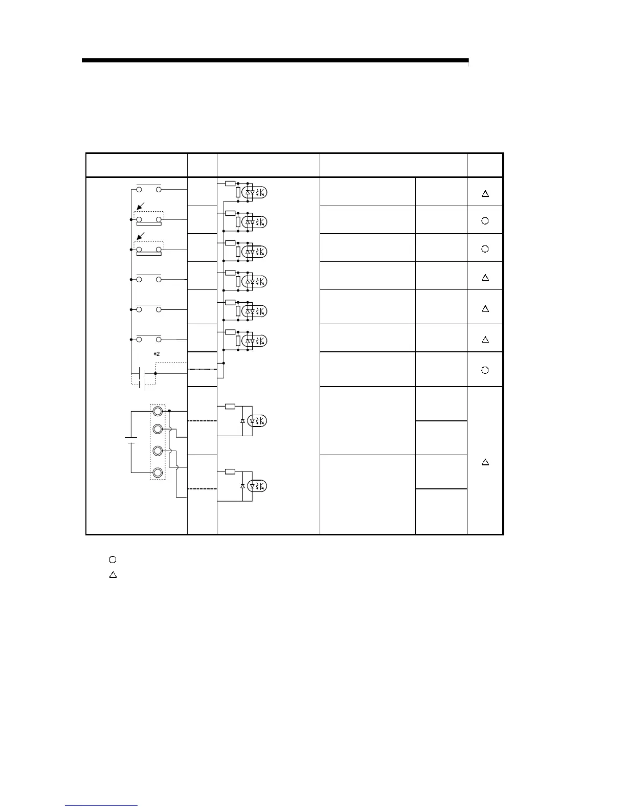
3.5.4 Interface internal circuit
The outline diagram of the internal circuit for the AD75 external device connection
interface is shown below.
External wiring
Pin
No.
Internal circuit Signal name
Need for
wiring *1
11
Near-point dog signal DOG
12
Upper limit signal FLS
13
Lower limit signal RLS
14
Stop signal STOP
15
Speed/position
changeover signal
CHG
16
External start signal STRT
35
36
Common COM
(+)
9
PULSER A+
(–)
27
Manual pulse generator
A phase
PULSER A–
(+)
10
PULSER B+
24VDC
When not using
upper limit switch
When not using
lower limit switch
5VDC
5V
0V
A
B
Manual pulse
generator
(MR-HDP01)
(–)
28
Manual pulse generator
B phase
PULSER B–
*1: The meaning of “O” and “
∆
” in the “need for wiring” column is as follows.
•
: Wiring is necessary in positioning.
•
: Perform wiring when necessary.
*2: The terminal connected to the common line may be either positive or negative.
 Loading...


