6 - 6
MELSEC-A
6 SEQUENCE PROGRAM USED FOR POSITIONING CONTROL
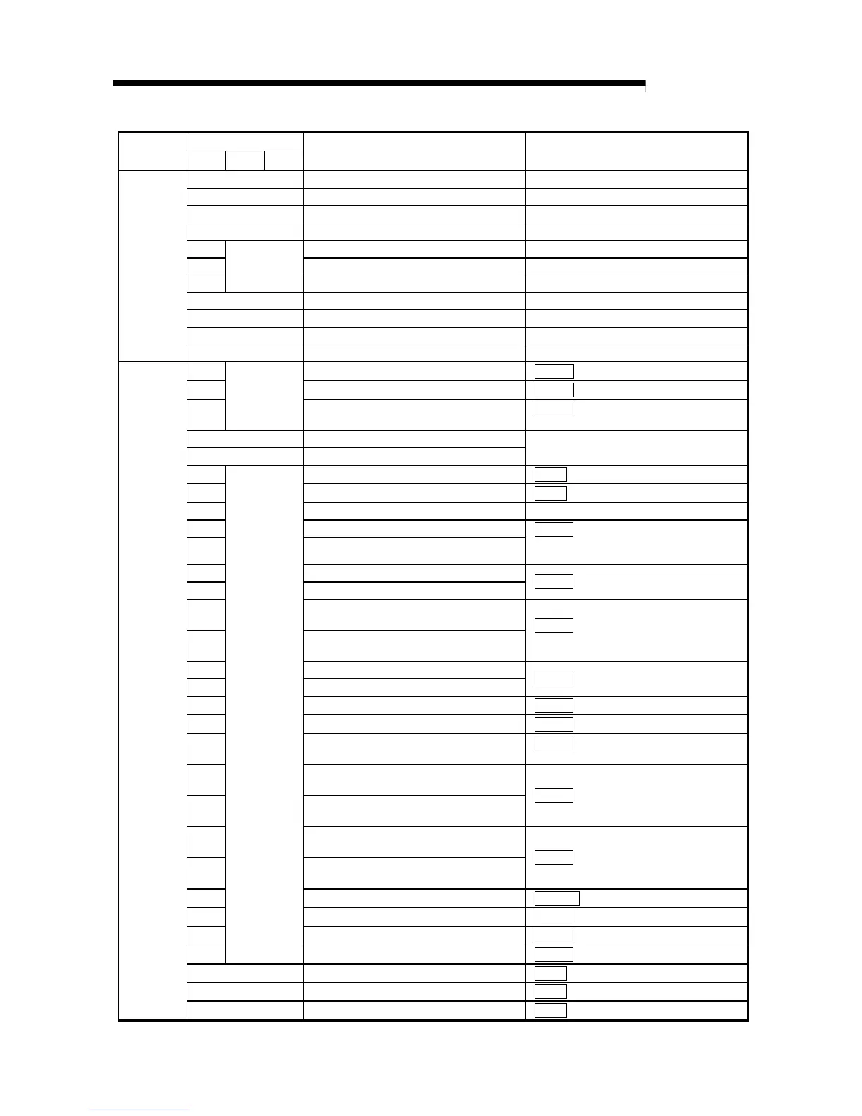
Device
Device
name
Axis 1 Axis 2 Axis 3
Application Details when ON
M26 Parameter initialization command pulse Parameter initialization commanded
M27 Parameter initialization command storage Parameter initialization command held
M28 Flash ROM write command pulse Flash ROM write commanded
M29 Flash ROM write command storage Flash ROM write command held
M30 Error code read complete Error code read completed
M31 Error reset Error reset completed
M32
–
Stop command pulse Stop commanded
M9028 Clock data read command Requesting clock data read
M9036 Always ON contact Always ON contact
M9038 1 scan ON after RUN 1 scan turned ON after RUN
Internal
relay
M9039 1 scan OFF after RUN 1 scan turned OFF after RUN
D0 Status information
( Md.40
Status)
D1 Zero point return request flag
( Md.40
Status (bit3))
D2
–
Zero point return request OFF results
( Cd.24
Zero point return request flag
OFF request)
D3 Date/hour data
D4 Minute/second data
PLC CPU clock data
D5 Clock data write request
( Cd.3
Clock data writing)
D6 Clock data write results
( Cd.3
Clock data writing)
D7 Positioning data No. Positioning data No.
D8 Movement amount (low-order 16 bits)
D9 Movement amount (high-order 16 bits)
( Cd.21
Speed/position changeover
control movement amount
change register)
D10 JOG operation speed (low-order 16 bits)
D11 JOG operation speed (high-order 16 bits)
( Cd.19
JOG speed)
D12
Manual pulse generator 1 pulse input
magnification (low-order)
D13
Manual pulse generator 1 pulse input
magnification (high-order)
( Cd.23
Manual pulse generator 1
pulse input magnification)
D14 Speed change value (low-order 16 bits)
D15 Speed change value (high-order 16 bits)
( Cd.16
New speed value)
D16 Speed change request
( Cd.17
Speed change request)
D17 Speed change result
( Cd.17
Speed change request)
D18 Override value
( Cd.18
Positioning operation speed
override)
D19
Acceleration time setting (low-order 16
bits)
D20
Acceleration time setting (high-order 16
bits)
( Cd.33
New acceleration time value)
D21
Deceleration time setting (low-order 16
bits)
D22
Deceleration time setting (high-order 16
bits)
( Cd.34
New deceleration time value)
D23 Torque output setting value
( Cd.101
Torque output setting value)
D24 Step valid flag
( Cd.26
Step valid flag)
D25 Step mode
( Cd.27
Step mode)
D26
–
Skip operation results
( Cd.29
Skip command)
D27 Target axis
( Cd.4
Target axis)
D28 Positioning data No.
( Cd.5
Positioning data No.)
Data
register
D29 Write pattern
( Cd.6
Write pattern)

 Loading...


