11 - 22
MELSEC-A
11 MANUAL CONTROL
11.3.3 Setting the required parameters for manual pulse generator operation
The "Parameters" must be set to carry out manual pulse generator operation.
The following table shows the setting items of the required parameters for carrying out
manual pulse generator operation. When only manual pulse generator operation will
be carried out, no parameters other than those shown below need to be set. (Use the
initial values or setting values within a range where no error occurs for trouble-free
operation.)
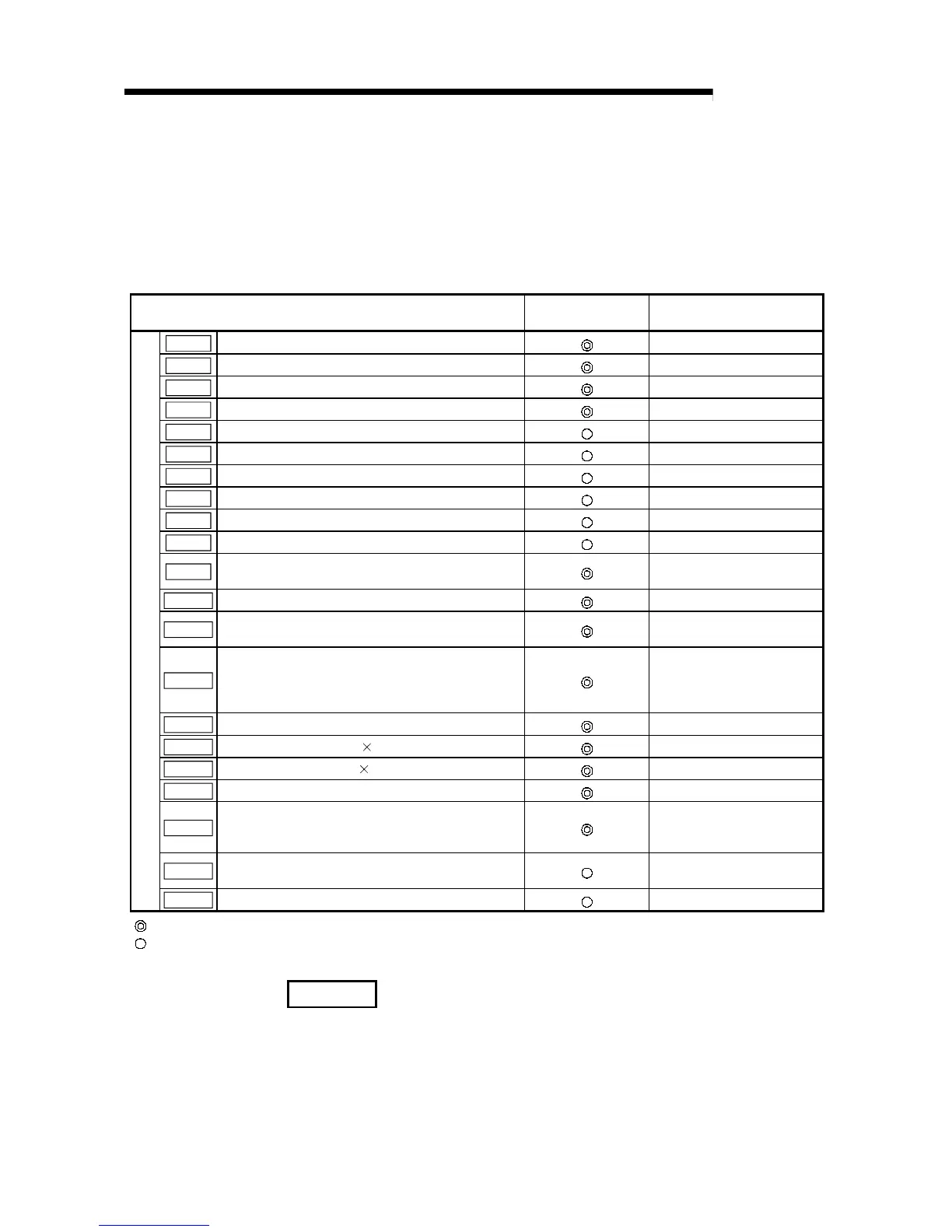
Setting item Setting requirement
Factory-set initial value
(setting details)
Pr.1
Unit setting
3 (pulse)
Pr.2
No. of pulses per rotation (Ap) (Unit: pulse)
20000
Pr.3
Movement amount per rotation (Al) (Unit: pulse)
20000
Pr.4
Unit magnification (Am)
1 (1-fold)
Pr.12
Backlash compensation amount (Unit: pulse)
0
Pr.13
Software stroke limit upper limit value (Unit: pulse)
2147483647
Pr.14
Software stroke limit lower limit value (Unit: pulse)
–2147483648
Pr.15
Software stroke limit selection
0 (current feed value)
Pr.16
Software stroke limit valid/invalid setting
0 (invalid)
Pr.18
Torque limit setting value (Unit: pulse)
300
Pr.23
Manual pulse generator selection
Axis 1 = 1, axis 2 = 2,
axis 3 = 3
Pr.100
Servo series
0 (MR-H-B (MR-H-BN)
Pr.101
Amplifier setting
0 (Absolute position detection
invalid)
Pr.102
Regenerative brake resistor
0000
H
(External regenerative
brake option not used,
external dynamic brake
invalid)
Pr.103
Motor type
0 (HA-SH Standard)
Pr.104
Motor capacity (unit: kW
100)
0
Pr.105
Motor speed (unit: r/min
10
-3
)
1
Pr.106
Feedback pulse
0 (16384pulse)
Pr.107
Rotation direction
0 (Forward run with
positioning address
increment)
Pr.108
Auto tuning
1 (Auto tuning for ordinary
operation)
Parameters
Pr.109
Servo response setting
1 (Normal (low response))
: Setting always required.
: Set according to requirements (Leave set to the initial value when not used.)
REMARK
•
Parameter settings work in common for all control using the AD75. When carrying
out other control ("main positioning control", "advanced positioning control", "zero
point return positioning control"), the respective setting items must also be
matched and set.
•
Parameters are set for each axis.
•
Refer to "Chapter 5 DATA USED FOR POSITIONING CONTROL" for setting
details.

 Loading...


