14 - 35
MELSEC-A
14 TROUBLESHOOTING
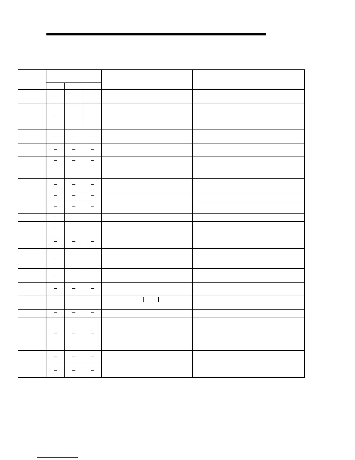
Relevant buffer memory
address
Axis 1 Axis 2 Axis 3
Checking method Remedy
Measure the input voltage (R, S, T) with a
voltmeter.
Review the power supply capacity.
Check if an instantaneous power failure
occurred.
Observe the input voltage with an
oscilloscope.
Measure the input voltage (R, S, T) with a
voltmeter.
Review the power supply capacity.
Change the unit. Change the unit.
Change the unit. Change the unit.
Change the unit. Change the unit.
Make visual check (to see if the connector is
disconnected or almost disconnected).
Connect correctly.
Change the servomotor. Change the servomotor.
Check the cable (change the cable).
Repair or change the cable (do not apply external force to
the cable).
Change the unit. Change the unit.
Check if the MC, etc. are operated at error
occurrence timing.
Take noise suppression measures.
Check the cable (change the cable).
Repair or change the cable (do not apply external force to
the cable).
Keep the power ON for a few minutes in the
error state and switch the power OFF, then
ON.
Keep the power ON for a few minutes to charge the super
capacitor, and switch the power OFF, then ON.
Perform initial setting of the zero point.
After switching the power OFF, measure the
voltage across the battery.
If the error still persists after the above
remedy.
Change the battery.
102 252 402
Check the setting of " Pr.102 Regenerative
brake resistor".
Set correctly.
Check the connection. Connect correctly.
1. Reconsider the regenerative brake torque
and the frequency of use of regenerative
braking.
2. Check the regenerative load factor in the
monitor mode.
1. Reduce the frequency of use of positioning.
2. Add the regenerative brake option.
3. Increase the servomotor capacity.
4. Reduce the load.
Check the resistance of the regenerative
power transistor using a tester.
Change the unit.
Check the resistance of the regenerative brake
resistor.
Change the regenerative brake resistor.

 Loading...


