4 - 13
MELSEC-A
4 INSTALLATION, WIRING AND MAINTENANCE OF THE PRODUCT
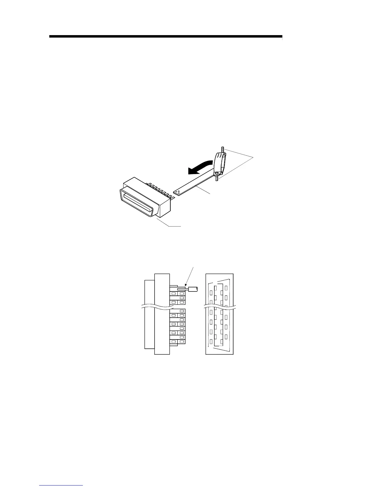
(2) Connecting the connector and wire
* Refer to section "3.5 Specifications of interfaces with external devices" when
connecting.
(a) Loosen the cable fixture screw B, pass the cable through, and
then tighten screw B.
(Screw B may be removed once, and then tightened after sandwiching the
cable.)
(Take care not to lose the screw and nut.)
B
Pass the cable through
Cable fixture
Connector
(b) Solder the wire onto the connector.
Connector pin layout
19
20
2
17
35
36
18
1
Solder
Wire
* The applicable size of the wire to be connected is "AWG#24 to #30
(approx. 0.05 to 0.2SQ)".

 Loading...


