11 - 18
TROUBLESHOOTING11.
<Calculation Example for Example 4>
Consider a switch with LED indicator connected to the A1SX40, giving a leakage current
of 3mA when a 24VDC power is tuTorned on.
(1) The 1.7mA OFF current of the A1SX40 is not satisfied. Hence,connect a resistor as
shown below.
(2) Calculate the resistor value R as indicated below.
To satisfy the 1.7mA OFF current of the A1SX40, the resistor R to be connected may
be the one where 0.63mA or more will fiow.
I
R :IZ=Z(Input impedance):R
(3) Connect a resistor of 1.5(k ) and 2 to 3(w) to a terminal which may cause an error,
since the power capacity of a resistor is resistor is seiected so that will be 3 to 5 times
greater than the actual power consumption.
(4) Also, OFF voltage when resistor R is conned will be as follows.
• This satisfies 6V or less OFF voltage of A1SX40.
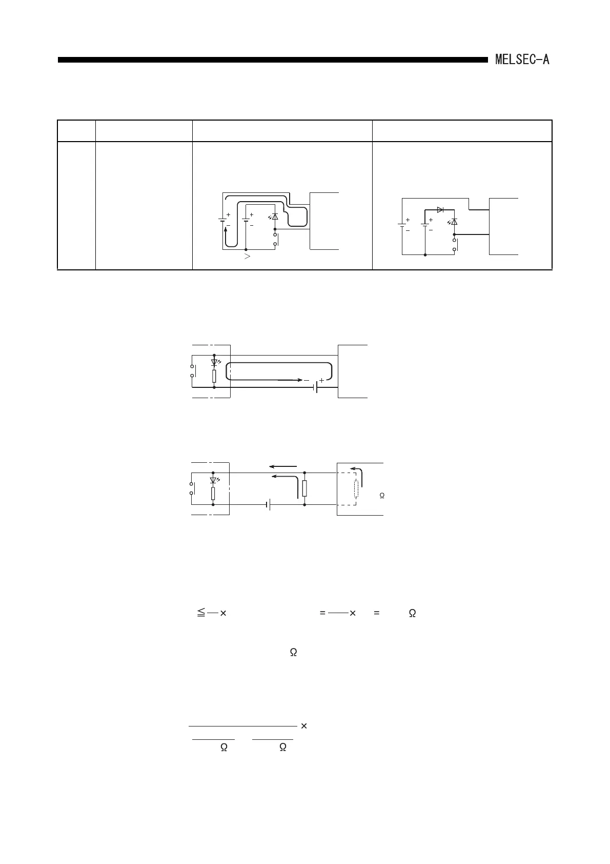
Table 11.2 Faults with the input circuit and the corrective actions (Continued)
Situation Cause Countermeasure
Example
5
Input signal does not
turn OFF.
• Sneak path due to the use of two power
supplies.
• Use only one power supply.
• Connect a diode to prevent the sneak path
(figure below).
DC input
Input
module
E1
E2
E1 E2
DC input
Input
module
E1
E2
A1SX40
24VDC
Leakage current 3mA
Input module
R
3mA
I
R=2mA
24VDC
I
Z=1mA
Input impedance
3.3k
A1SX40
R Z(Input impedance) 3.3 1.65[k ]
I R
I Z
2.0
1.0
3[mA] = 3.09[V]
1
1.5[k ]
1
3.3[k ]
1
+
 Loading...


