4 - 13
4. CPU MODULE
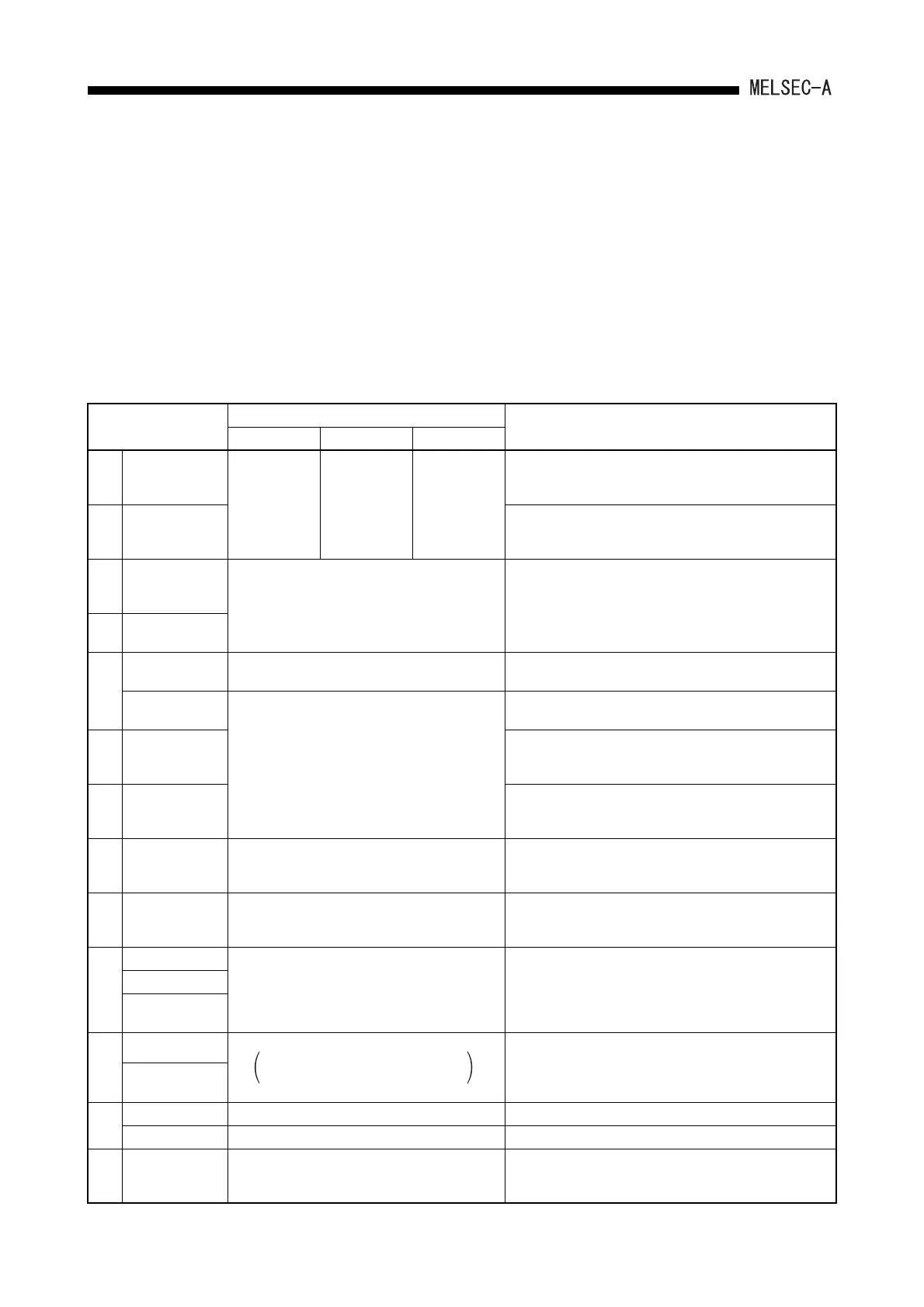
4.1.5 Device list
Device means a general name for such as a contact, coil and timer used on the program
operations in a programmable controller.
The following shows usage ranges and device names of the programmable controller.
For "*" in the devices below, they can be used by setting the parameters on each
peripheral device. Also, they can be changed the usage ranges assignment.
Set the parameters depending on the usage system and contents of the programs.
For the detailed setting for parameters, refer to Section 4.2.1 "List of parameter setting
range".)
Device list
Device
Usage Range (points)
Description of Device
A1SJHCPU(S8) A1SHCPU A2SHCPU(S1)
X Input
X/Y0 to X/YFF
(256 points)
X/Y0 to X/YFF
(256 points)
A2SHCPU:
X/Y0 to X/Y1FF
(512 points)
A2SHCPU-S1:
X/Y0 to X/Y3FF
(1024 points)
Used for the supply programmable controller commands and data
from the external devices such as push buttons, select switches,
limit switches and digital switches.
Y Output
Used for the output control results of the program to the external
devices such as solenoids, magnetic switches, signal lights and
digital display device.
X Input
X/Y0 to X/Y7FF (2048 points)
• Possible to use in a program from the I/O points usage range for
each PLC (described above) up to 2048 points.(External output
is not allowed.)
Y Output
• Allocates for remote I/O of MELSECNET(B) and for auto refresh
of CC-Link.
M
Special relay M9000 to M9255 (256 points)
An auxiliary relay that is used in a programmable controller set in
advance for a special application.
*Internal relay
M/L/S0 to M/L/S2047 (2048 points)
2048 points as a total of M, L, S
An auxiliary relay in a programmable controller that cannot output
directly to external devices.
L *Latch relay
An auxiliary relay in a programmable controller that cannot output
directly to the external devices. Has the power failure
compensation function.
S *Step relay
Used in the same manner as the internal relay (M).
Used as a relays to indicate the stage number of process stepping
program, etc.
R Link relay B0 to B3FF (1024 points)
An internal relay for data link. Cannot output to external
devices.The range not set by the link parameters can be used as a
substitute for a data register.
F Annunciator F0 to F255 (256 points)
For error detection. A fault finding program is created in advance,
and if it becomes ON during RUN, the number is stored in a special
register D.
T
*100ms timer
T0 to T255 (256 points)
Up-timing-timer. There are three kinds: 100ms timer, 10ms timer
and 100ms retentive timers.
*10ms timer
*100ms retentive
timer
C
*Counter
C0 to C255 (256 points)
Interrupt counter can be used by setting
parameters.
Up-timing
There are two kinds: up-timing counter used in programmable
controller programs, interrupt counter used in counting the number
of interrupts.
*Interrupt counter
D
Data register D0 to D1023 (1024 points) Memory that stores data inside the programmable controller.
Special register D9000 to D9255 (256 points) Data memory set up in advance for the special application
W Link register W0 to W3FF (1024 points)
Register for a data link
The range not set by the link parameters can be used as a
substitute for a data register.
 Loading...


