24
WT09050X01
9-4. Pipe connection example
9-4-1. Example of pipe connection between an outdoor unit and HBC controller, and
between an HBC controller and indoor unit
h1
h2
g
f
H H'
h
1
A
e
dc
b'
a
b
Ⓐ
Ⓒ
Ⓓ
Ⓑ Ⓑ Ⓑ Ⓑ Ⓑ
Ⓔ
Ⓖ
Ⓕ
Ⓑ
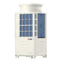
Ⓐ Outdoor unit
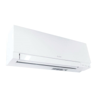
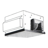
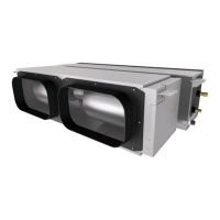
Ⓑ Indoor unit
Ⓒ Main HBC controller
Ⓓ Sub HBC controller
Ⓔ 2-Branch Joint Pipe (not supplied)
Ⓕ Joint Pipe Kit (not supplied)
Ⓖ Max. 3 sets for 1 port (Total capacity ≤ WP80)
Ⓐ
Ⓒ
Ⓑ
Ⓐ HBC controller
Ⓑ Joint Pipe Kit (not supplied)
Ⓒ Increaser (20A-to-32A) (not supplied)
Item Piping portion Allowable value
Pipe length
Between outdoor unit and HBC controller (refrigerant pipework) A 110 m (360 ft) or below
Water pipework between indoor units and HBC controller f + g 60 m (196 ft) or below
Difference of
elevation
Between HBC controller and outdoor
units
Outdoor unit above HBC
controller
H 50 m (164 ft) or below
Outdoor unit below HBC
controller
H' 40 m (131 ft) or below
Between indoor units and HBC controller h
1
15 m (10 m
*1
)
(49 ft (32 ft
*1
)) or below
Between indoor units h
2
15 m (10 m
*1
)
(49 ft (32 ft
*1
)) or below
*1 The values marked with *1 indicate the values when the total indoor unit capacity exceeds 130% of outdoor unit capacity.
(~(E)M300)
(WP100-WP125)
(WP10-WP80)
CMB-WM108V-AA + CMB-WM108V-AB
(CMB-WM1016V-AA) (CMB-WM1016V-AB)
(WP100 and WP125 models)
Fig. 9-4-1
 Loading...


