Do you have a question about the Mitsubishi DA-C20 and is the answer not in the manual?
Details technical specifications for the FM tuner section according to IHF standards, covering sensitivity and performance metrics.
Details technical specifications for the FM tuner section according to DIN standards, covering sensitivity and performance metrics.
Details technical specifications for the AM tuner section according to IHF standards, covering sensitivity and performance metrics.
Details technical specifications for the AM tuner section according to DIN standards, covering sensitivity and performance metrics.
Outlines input sensitivity, output level, impedance, tone control range, and noise specifications for the preamplifier.
Directive to always turn off power before connecting/disconnecting to prevent speaker damage from click noise.
Warning against incorrect or short-circuited connections to ensure stable sound and prevent damage.
Guidance on making correct input terminal connections to prevent hum and protect speakers.
Recommendation to use short, shielded wires for input connections to maintain signal quality.
Advice to short unused PHONO terminals to prevent noise and clicks during operation.
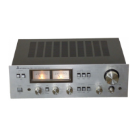
Details the function of front panel elements including IF BAND, MUTING, MODE, TUNING, and tone controls.
Describes the speaker selection switches and their functionality when used with power amplifiers.
Explains the operation of the input selector for choosing program sources like PHONO, TUNER, and AUX.
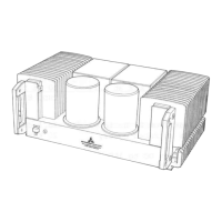
Instructions for removing the outer casing parts using designated screws.
Steps for removing the front panel, including controls and fixing screws.
Procedures for detaching the tuner section from the chassis by removing securing screws.
Guidance on how to disassemble the preamplifier section following similar steps.
Steps for adjusting the PA-66 board using VR501 to achieve specified voltage outputs.
Steps for adjusting the PA-67 board using VR601 to achieve specified voltage outputs.
Procedure for tuning and adjusting the FM Mono section for optimal signal reception and center meter indication.
Steps for calibrating the FM MPX section, including stereo reception, pilot signal, and muting.
Instructions for adjusting the AM section's tracking for maximum output across the frequency band.
Diagram and steps for threading the dial cable to ensure proper tuning mechanism operation.
Diagram showing the arrangement of components on the PA-67 printed circuit board.
Diagram showing the arrangement of components on the PA-66 printed circuit board.
Detailed circuit diagrams for the FM/AM tuner RF, Mix, Local Osc, and IF amplifier stages.
Circuit diagrams for FM IF AMP, Discriminator, Stereo Indicator, Lock Indicator, and MPX sections.
Diagrams detailing the Preamplifier, Equalizer Amp, Tone Amp, and Selector circuitry.
Lists transistors, diodes, ICs, switches, and potentiometers with their corresponding part numbers.
Lists knobs, meters, lamps, sockets, jacks, and packing materials with part numbers.
Details the packing bag, box, and cushion used for secure packaging.
| Brand | Mitsubishi |
|---|---|
| Model | DA-C20 |
| Category | Amplifier |
| Language | English |