MPI <6A1> -
Troubleshooting
13A-185
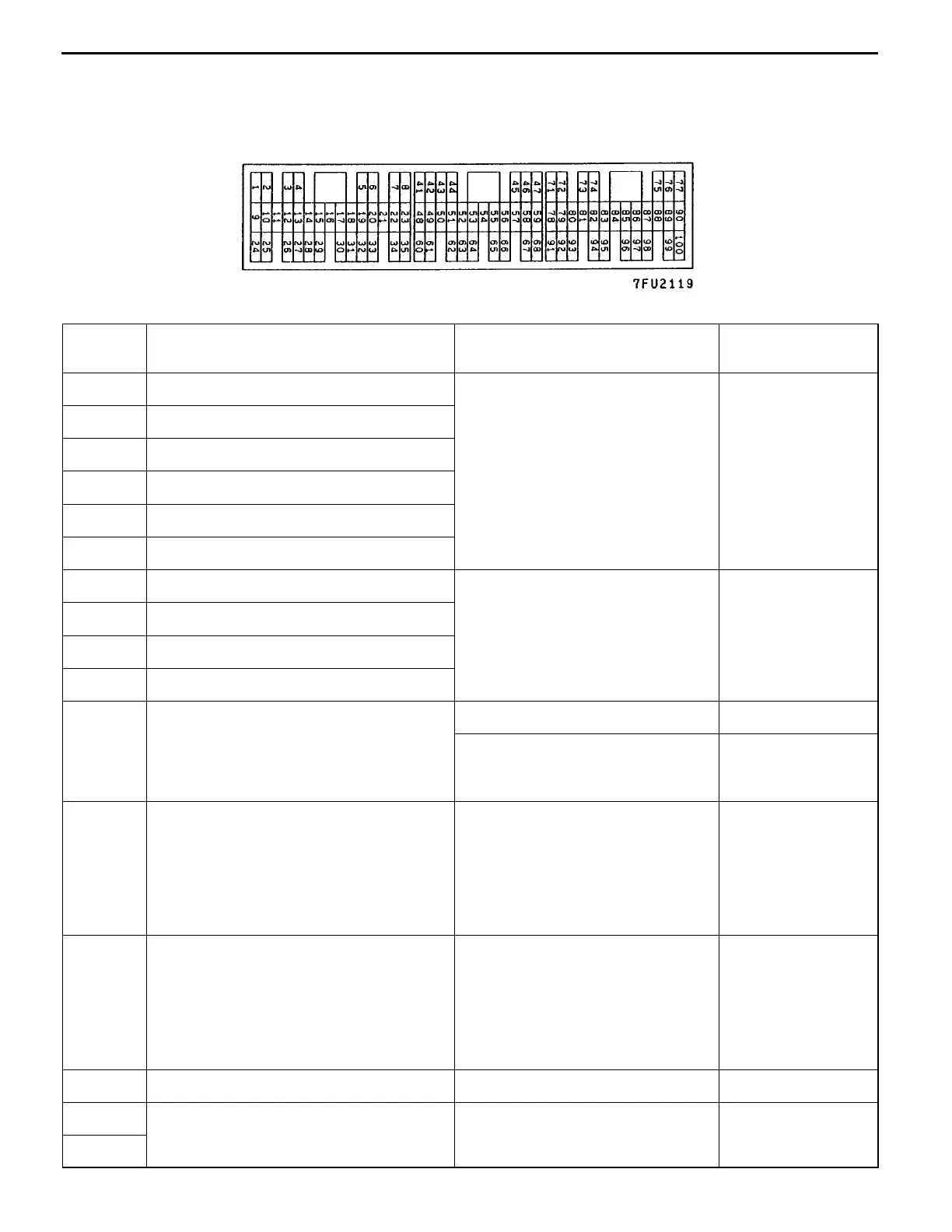
CHECK AT THE ENGINE-ECU TERMINALS
TERMINAL VOLTAGE CHECK CHART
Engine-ECU Connector Terminal Arrangement
Terminal
No.
Check item Check condition (Engine condition) Normal condition
1 No. 1 injector While engine is idling after having From 11 - 14 V,
9 No. 2 injector
warmed up, suddenly depress the
accelerator pedal.
momentarily drops
slightly
24 No. 3 injector
2 No. 4 injector
10 No. 5 injector
25 No. 6 injector
14 Stepper motor coil <A1> Engine: Soon after the warmed up 10 - 15 V « 0-6V
28 Stepper motor coil <A2>
engine is started (Changes repeated-
ly)
15 Stepper motor coil <B1>
29 Stepper motor coil <B2>
6 EGR control solenoid valve Ignition switch: ON System Voltage
While engine is idling, suddenly
depress the accelerator pedal.
From system
voltage, momentari-
ly drops
8 Alternator G terminal
D
Engine: Warm up, and then
idling
D
Radiator fan: Not operating
D
Headlamp: OFF ® ON
D
Stop lamp: OFF ® ON
D
Rear defogger switch:
OFF ® ON
Voltage increases
by 0.2 - 3.5 V
52 Alternator FR terminal
D
Engine: Warm up, and then
idling
D
Radiator fan: Not operating
D
Headlamp: OFF ® ON
D
Stop lamp: OFF ® ON
D
Rear defogger switch:
OFF ® ON
Voltage decrease
11 Power transistor unit Engine r/min: 3,000 r/min 0.3 - 3.0 V
47 Power supply Ignition switch: ON System voltage
59
 Loading...