MPI <6A1> -
On-vehicle Service
13A-193
ON-VEHICLE SERVICE
OXYGEN SENSOR CHECK
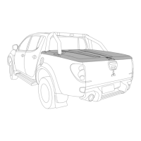
<Left bank oxygen sensor (front) and right bank
oxygen sensor (front)>
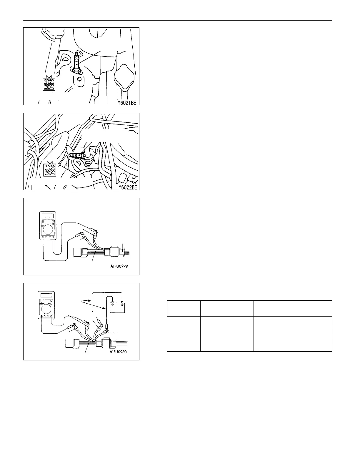
1. Disconnect the oxygen sensor connector and connect
the special tool (test harness) to the connector on the
oxygen sensor side.
2. Make sure that there is continuity (4.5 - 8.0
W
at 20
_
C)
between terminal 1 (red clip of special tool) and terminal
3 (blue clip of special tool) on the oxygen sensor connector.
3. If there is no continuity, replace the oxygen sensor.
4. Warm up the engine until engine coolant is 80
_
C or higher.
5. Use a jumper wire to connect terminal 1 (red clip) of
the oxygen sensor connector to the battery (+) terminal
and terminal 3 (blue clip) to the battery ( - ) terminal.
Caution
Be very careful when connecting the jumper wire;
incorrect connection can damage the oxygen sensor.
6. Connect a digital voltage meter between terminal 2 (black
clip) and terminal 4 (white clip).
7. While repeatedly racing the engine, measure the oxygen
sensor output voltage.
Standard value:
Engine Oxygen sensor
output voltage
Remarks
When
racing the
engine
0.6 - 1.0 V If you make the air/fuel ratio
rich by racing the engine
repeatedly, a normal oxy-
gen sensor will output a
voltage of 0.6 - 1.0 V.
8. If the sensor is defective, replace the oxygen sensor.
NOTE
For removal and installation of the oxygen sensor, refer
to GROUP 15 - Exhaust Pipe and Main Muffler.
Left bank oxygen
sensor (front)
Equipment side connector
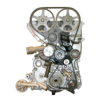
Equipment side connector
Right bank oxygen
sensor (front)
Blue
Red
MD998464
Oxygen sen-
sor equipment
side connector
Jumper
wire
Black
Red
White
MD998464
Blue
 Loading...