MPI <4G6> -
Troubleshooting
13A-28
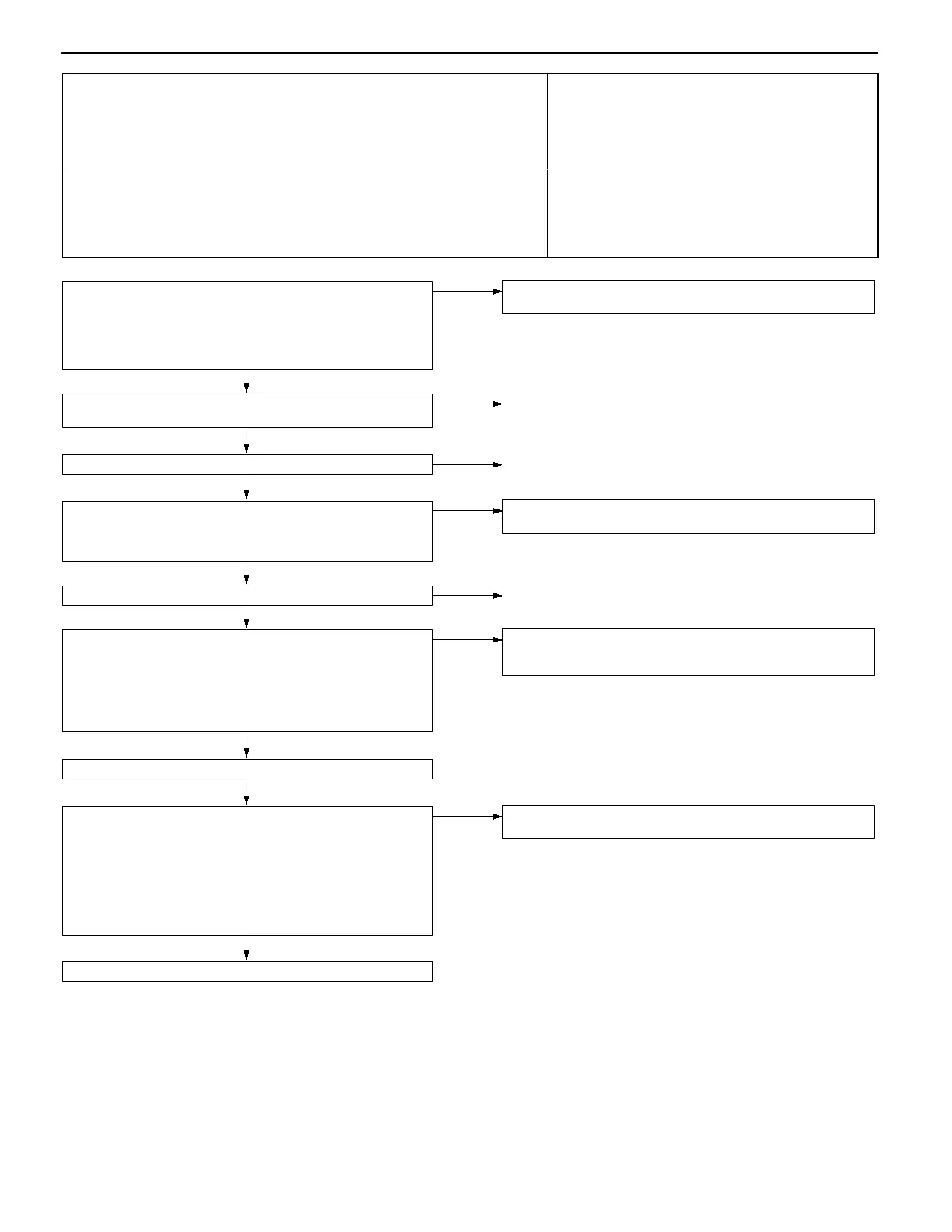
Code No. P0201 No. 1 injector system
Code No. P0202 No. 2 injector system
Code No. P0203 No. 3 injector system
Code No. P0204 No. 4 injector system
Probable cause
Range of Check
D
Engine speed is approx. 50 - 1,000 r/min
D
The throttle position sensor output voltage is 1.15 V or less.
D
Actuator test by MUT-
II
is not carried out.
Set Conditions
D
Surge voltage of injector coil is not detected for 4 seconds.
D
Malfunction of the injector
D
Improper connector contact, open circuit or short-cir-
cuited harness wire of the injector circuit
D
Malfunction of engine-ECU <M/T>
D
Malfunction of engine-A/T-ECU <A/T>
NG
Replace the engine-ECU <M/T> or engine-A/T-ECU <A/T>.
NG
Use an analyzer to measure the signal waveform at injector
connector B-02, B-03, B-05, B-36.
D
Use a test harness (MB991348) to connect the connector, and
measure at the pick-up harness side.
D
Engine: Idling
D
The voltage between terminal 2 and earth
OK:
A normal waveform should be displayed as described
on P.13A-88 (INSPECTION PROCEDURE USING
AN ANALYZER).
OK
Intermittent malfunction (Refer to GROUP 00 - Points to Note for
Intermittent Malfunctions.)
OK
Check trouble symptoms.
OK
Measure at the engine-ECU connector C-34 <M/T> or engine-A/T-
ECU connector C-177<A/T>.
D
Disconnect the connector, and measure at the harness side.
D
Voltage between 1, 2, 14, 15 and earth (Ignition switch: ON)
<M/T>
D
Voltage between 1, 2,9, 24 andearth(Ignitionswitch:ON)<A/T>
OK:
System voltage
NG
Check the harness wire between the engine-ECU <M/T> or
engine-A/T-ECU <A/T> and the injector connector, and repair if
necessary.
OK
Check the following connector:
C-34 <M/T>, C-177 <A/T>
NG
Repair
OK
Measure at the injector connector B-02, B-03, B-05, B-36.
D
Disconnect the connector, and measure at the harness side.
D
Voltage between 1 and earth (Ignition switch: ON)
OK:
System voltage
NG
Check the harness wire between the engine control relay and the
injector connector, and repair if necessary.
OK
Check the injector. (Refer to P.13A-93*.)
NG
Replace
NG
Check the following connectors:
B-02, B-03, B-05, B-36
NG
Repair
MUT-
II
Actuator Test
01 No. 1 injector
02 No. 2 injector
03 No. 3 injector
04 No. 4 injector
OK:
The idling condition should change
OK
Intermittent malfunction
(Refer to GROUP 00 - Points to Note for Intermittent Malfunctions.)
NOTE:
*: Refer to the ’97 GALANT Workshop Manual (Pub. No. PWDE9611)
 Loading...