MPI <4G6> -
Troubleshooting
13A-30
NG
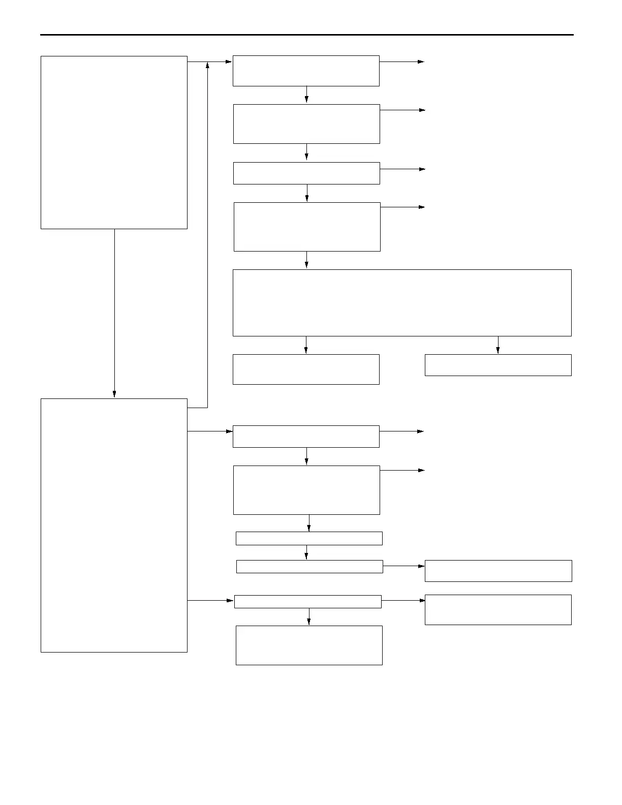
Check the spark plug and the
ignition coil for a defective cylinder.
(Refer to GROUP 16 - Ignition
System.)
Check the trouble symptoms.
NG
Replace the engine-ECU <M/T> or
engine-A/T-ECU <A/T>.
OK
Check the harness wire between the
engine-ECU <M/T> or
engine-A/T-ECU <A/T> and the
ignition coil connector for defective
cylinder.
NG
Repair
OK
Check the following connector:
C-34 <M/T>, C-177 <A/T>
NG
Repair
MUT-
II
Actuator Test
01 No. 1 injector
02 No. 2 injector
03 No. 3 injector
04 No. 4 injector
OK:
The idling condition should
change.
Reference
When the cylinder (defective
cylinder) where idling condition does
not change is detected after
suspending the injector, go to (1)
and inspect the spark plug, the
ignition coil, the connector, and the
harness of the defective cylinder.
(When more than one cylinder are
detected, inspect all of them.)
When all the cylinders are OK, go to
(2).
(1)
Check the following connectors:
The ignition coil connectors for a
defective cylinder (B-01, B-11).
NG
Repair
OK
Check the spark plug and the
ignition coil for a defective cylinder.
(Refer to GROUP 16 - Ignition
System.)
NG
Replace
OK
Use an analyzer to measure the signal waveform at engine-ECU connector C-34 <M/T>
or engine-A/T-ECU connector C-177 <A/T>.
D
Engine: Idling
D
The voltage between the ignition coil primary signal terminal for a defective cylinder
and earth
OK:
A normal waveform should be displayed as described on P.13A-88* (Inspection
Procedure Using an Analyzer).
OK
Repair the ignition coil assembly for
a defective cylinder and the spark
plug.
NG
Replace the engine-ECU <M/T> or
engine-A/T-ECU <A/T>.
(2)
Use an analyzer to measure the
signal waveform at the ignition failure
sensor connector B-105.
D
Use test harness (MB991536) to
connect the connector, and
measure at the pick-up harness.
D
Engine: Idling
D
The voltage between terminal 2
and earth
OK:
A normal waveform should
be displayed as described
on P.13A-88* (INSPECTION
PROCEDURE USING AN
ANALYZER).
Reference
When a normal waveform is
displayed, compare it with that of the
ignition coil primary signal at the
engine-ECU terminal <M/T> or
engine-A/T-ECU <A/T> to determine
the cylinder (defective cylinder) with
an abnormal waveform.
®
When one or more cylinders are
abnormal, go to (1)
®
When all of the cylinders are
abnormal, go to (3)
®
When a normal waveform is
displayed, go to (4).
(3)
Check the following connectors:
C-38 <M/T>, C-176 <A/T>, B-105
NG
Repair
OK
Check the harness wires between
the ignition failure sensor and the
engine-ECU <M/T> or
engine-A/T-ECU <A/T>, and between
the ignition failure sensor and earth.
NG
Repair
OK
Repair the ignition failure sensor.
(4)
Check the trouble symptoms.
OK
Intermittent malfunction
(Refer to GROUP 00 - Points to
Note for Intermittent Malfunctions.)
(1)
 Loading...