MPI <4G6> -
Troubleshooting
13A-33
OK
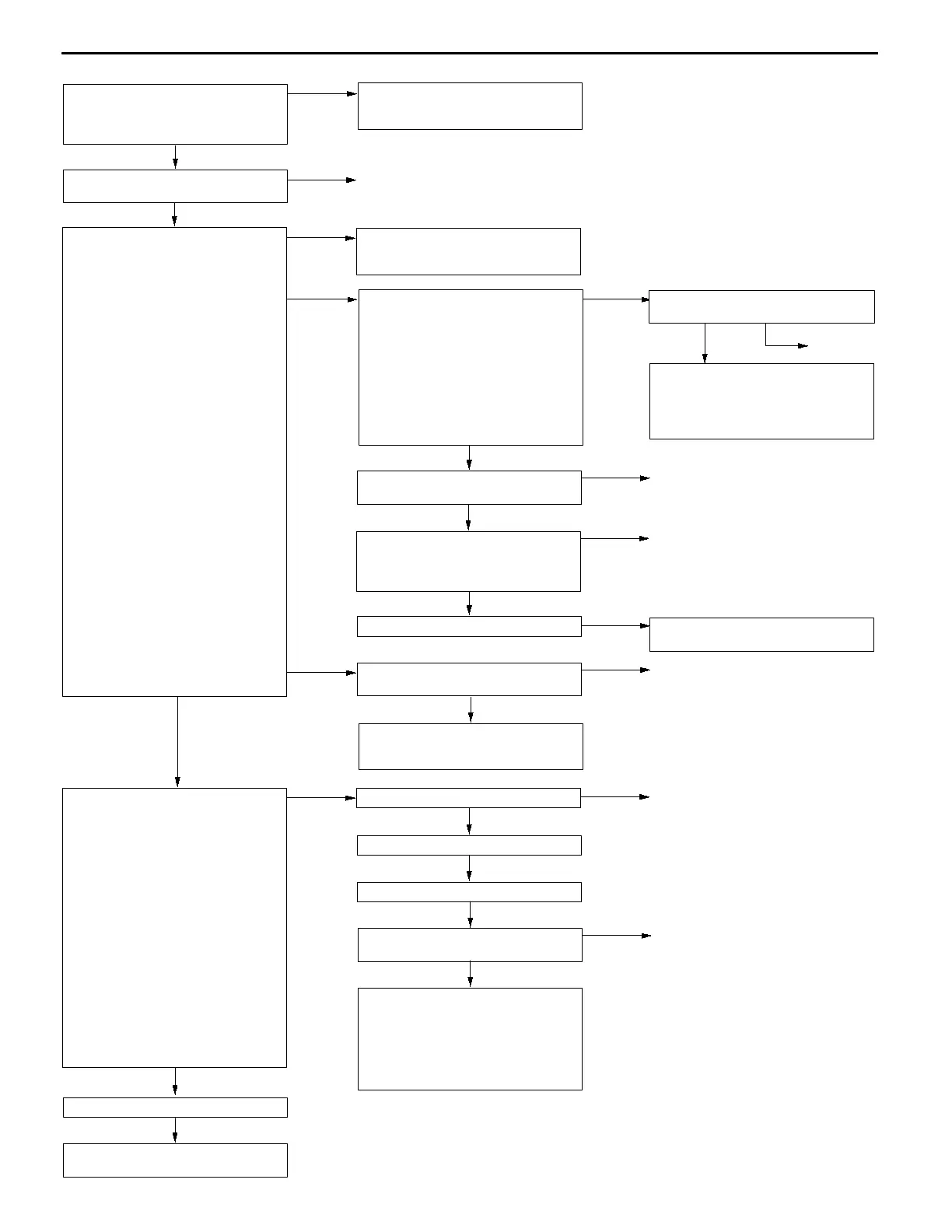
Check the trouble symptoms.
OK
Check the harness wire between the
crank angle sensor and the engine
control relay, and repair if necessary.
Check the following connector:
C-31
NG
Repair
OK
Check the trouble symptoms.
NG
Replace the engine-ECU <M/T> or
engine-A/T-ECU <A/T>.
(3) NG
OK
Use an analyzer to measure the
output waveform at the crank angle
sensor connector B-77.
D
Use the test harness (MB991658)
to connect the connector, and
measure at the pick-up harness
side.
D
Engine: Idling
D
The voltage between terminal 3
and earth
OK:
A normal waveform should
be displayed as described
on P.13A-88 (Inspection
Procedure Using an Ana-
lyzer). Its maximum value
should be 4.8 V or more,
and its minimum value
should be 0.6 V or less
with no noise in waveform.
NG
Check the crank angle sensor vane.
NG
Replace
OK
Replace the crank angle sensor.
Check the trouble symptoms.
NG
Check the following connector:
C-40 <M/T>, C-176 <A/T>
NG
Repair
OK
Check the harness wires between
the crank angle sensor and the
engine-ECU <M/T> or
engine-A/T-ECU <A/T>, crank angle
sensor and the engine control relay,
and the crank angle sensor and
earth. Then, repair if necessary.
NG
Replace the engine-ECU <M/T> or
engine-A/T-ECU <A/T>.
OK
Check the harness wire between the
crank angle sensor and the
engine-ECU <M/T> or
engine-A/T-ECU <A/T>, and repair if
necessary.
OK
Measure at the crank angle sensor
connector B-77.
D
Disconnect the connector and
measure at the harness side.
(1) The resistance between terminal
1 and earth
OK:
2
W
or less
(2) The voltage between terminal 2
and earth
(Ignition switch: ON)
OK:
4.8 - 5.2 V
(3) The voltage between terminal 3
and earth
(Ignition switch: ON)
OK:
System voltage
(1) NG
Check the harness between the
crank angle sensor and earth, and
repair if necessary.
NG
Repair
NG
Check the following connector:
C-40 <M/T>, C-176 <A/T>
NG
Repair
NG
Check the following connector:
B-77
NG
Repair
(2) NG
Measure at engine-ECU connector
C-40 <M/T> or engine-A/T-ECU
connector C-176 <A/T>.
D
Measure the voltage at the
engine-ECU terminal <M/T> or
engine-A/T-ECU terminal <A/T>.
D
Disconnect the connector B-77
D
Ignition switch: ON
D
The voltage between terminal 89
<M/T>, 45 <A/T> and earth
OK:
4.8 - 5.2 V
OK
Check the following connector:
C-40 <M/T>, C-176 <A/T>
OK
Check the harness wire between the
crank angle sensor and the
engine-ECU <M/T> or
engine-A/T-ECU <A/T>.
NG
Repair
MUT-
II
Data list
22 Crank angle sensor
OK:
Refer to P.13A-75, DATA
LIST REFERENCE TABLE.
OK
Intermittent malfunction
(Refer to GROUP 00 - Points to
Note for Intermittent Malfunctions.)
 Loading...