Requirement for Compliance with LVD directive
The following products have shown compliance through direct
testing (of the identified standards below) and design analysis
(through the creation of a technical construction file) to the European
Directive for Low Voltage (73/23/EEC) when used as directed by the
appropriate documentation.
Type : Programmable Controller (Open Type Equipment)
Models : MELSEC FX3U series manufactured
from May 1st, 2005 FX3U-ËËMR/ES(-A)
Where ËË indicates:16,32,48,64,80
from November 1st, 2005 FX3U-ËËMT/ES(-A)
FX3U-ËËMT/ESS
Where ËË indicates:16,32,48,64,80
from February 1st, 2006 FX3U-128MR/ES(-A)
FX3U-128MT/ES(-A)
FX3U-128MT/ESS
FX3U-ËËMR/DS
Where ËË indicates:16,32,48,64,80
Models :MELSEC FX2N series manufactured
from July 1st, 1997 FX2N-ËËER-ES/UL FX2N-ËËET-ESS/UL
Where ËË indicates:32,48
FX2N-16EYR-ES/UL
from April 1st, 1998 FX2N-48ER-DS
from August 1st, 1998 FX2N-48ER-UA1/UL
from August 1st, 2005 FX2N-8ER-ES/UL FX2N-8EYR-ES/UL
For the products above, PLCs manufactured
before March 31st, 2002 are compliant with IEC1010-1
from April 1st, 2002 to April 30th, 2006 are compliant with EN61131-
2:1994+A11:1996+A12:2000
after May 1st, 2006 are compliant with EN61131-2:2003
Caution for compliance with EC Directive
Installation in Enclosure
Programmable logic controllers are open-type devices that must be
installed and used within conductive control boxes. Please use the
FX3U Series programmable logic controllers while installed in
conductive shielded control boxes. Please secure the control box lid
to the control box (for conduction). Installation within a control box
greatly affects the safety of the system and aids in shielding noise
from the programmable logic controller.
Caution for Analog Products in use
The analog special adapters have been found to be compliant to the
European standards in the aforesaid manual and directive. However,
for the very best performance from what are in fact delicate
measuring and controlled output device Mitsubishi Electric would like
to make the following points;
As analog devices are sensitive by nature, their use should be
considered carefully. For users of proprietary cables (integral with
sensors or actuators), these users should follow those
manufacturers installation requirements.
Mitsubishi Electric recommend that shielded cables should be used.
If NO other EMC protection is provided, then users may experience
temporary induced errors not exceeding +10%/-10% in very heavy
industrial areas.
However, Mitsubishi Electric suggest that if adequate EMC
precautions are followed with general good EMC practice for the
users complete control system, users should expect normal errors
as specified in this manual.
- Sensitive analog cable should not be laid in the same trunking
or cable conduit as high voltage cabling. Where possible users
should run analog cables separately.
- Good cable shielding should be used. When terminating the
shield at Earth - ensure that no earth loops are accidentally
created.
- When reading analog values, EMC induced errors can be
smoothed out by averaging the readings. This can be achieved
either through functions on the analog special adapter/block or
through a users program in the FX3U Series PLC main unit.
Associated manuals
FX3U Series PLC (main unit) comes with this document (hardware
manual).
For a detailed explanation of the FX3U Series hardware and
information on instructions for PLC programming and special
extension unit/block, refer to the relevant documents.
How to obtain manuals
For the necessary product manuals or documents, consult with the
Mitsubishi Electric dealer from where you purchase your product.
Standard Remark
EN61131-2:2003
Programmable controllers
-Equipment
requirements and tests
The equipment has been assessed
as a component for fitting in a
suitable enclosure which meets the
requirements of EN61131-2:2003
Standard Remark
IEC1010-1:1990
/A1:1992
Safety requirements for
electrical equipment for
measurement, control, and
laboratory use
- General requirements
The equipment has been assessed
as a component for fitting in a
suitable enclosure which meets the
requirements of IEC 1010-1:
1990+A1:1992
EN61131-2:1994 :2003
/A12:2000
/A11:1996
Programmable controllers
-Equipment
requirements and tests
The equipment has been assessed
as a component for fitting in a
suitable enclosure which meets the
requirements of EN61131-2:
1994+A11:1996+A12:2000, :2003
Manual name Manual No. Description
FX3U Series
User's Manual
- Hardware
Edition
JY997D16501
MODEL CODE:
09R516
Explains FX3U Series PLC
specification details for I/O,
wiring, installation, and
maintenance.
FX3U/FX3UC
Series
Programming
Manual
- Basic & Applied
Instruction Edition
JY997D16601
MODEL CODE:
09R517
Describes PLC
programming for basic/
applied instructions STL/
SFC programming and
devices.
FX Series User’s
Manual - Data
Communication
Edition
JY997D16901
MODEL CODE:
09R715
Explains N:N link, parallel
link, computer link, no
protocol communication by
RS instructions/FX2N-
232IF.
FX3U / FX3UC
Series
User's Manual
- Analog Control
Edition
JY997D16701
MODEL CODE:
09R619
Describes specifications for
analog control and
programming methods for
FX3U / FX3UC Series PLC.
FX3U / FX3UC
Series
User's Manual
- Positioning
Control Edition
JY997D16801
MODEL CODE:
09R620
Explains the specifications
for positioning control of
FX
3U / FX3UC Series and
programming procedures
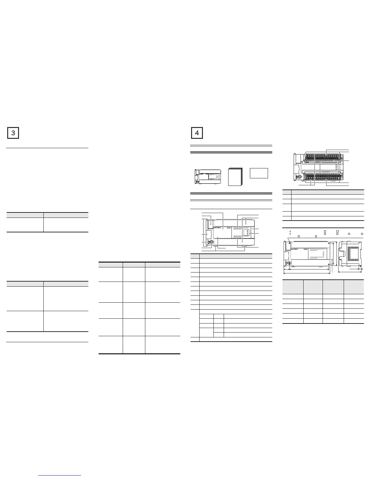
Incorporated Items
Check if the following product and items are included in the package:
1. Outline
1.1 Part names
With terminal cover open
1.2 External dimensions and weight
Product Manual Dust proof sheet
(1 sheet)
No. Name
[1] Top cover
[2] Battery cover
[3] Special adapter connecting hooks (2 places)
[4] Expansion board dummy cover
[5] RUN/STOP switch
[6] Peripheral device connecting connector
[7] DIN rail mounting hooks
[8] Model name (abbreviation)
[9] Input display LEDs (Red)
[10] Terminal block covers
[11] Extension device connecting connector cover
[12]
Operation status display LEDs
POWER Green On while power is on the PLC.
RUN Green On while the PLC is running.
BATT Red Lights when the battery voltage drops.
ERROR
Red Flashing when a program error occurs.
Red Lights when a CPU error occurs.
[13] Output display LEDs (Red)
FX
3U
-48MR/ES
FX
3U
-48MFX
3U
ERROR
RUN
BATT
POWER
R
0312
IN
OUT
645
21
7
20 2422 23 2625
10 11 1312 1614 15 17
27
0312 645
21
7
20 2422 23 2625
10 11 1312 1614 15 17
27
Y12Y10 Y16Y14 Y22Y20 Y26 COM5
COM1
Y24Y6
Y4Y2Y0
Y7 Y11 Y13Y5
COM2
Y3
Y1
COM3 Y15 Y17COM4 Y23 Y25 Y27Y21
X5
X0
X1
X2
X3 X7
X11
X13
X40VS/S
N 24V
X6 X10 X12 X14 X16 X20
L X27X23 X25X15 X17 X21
X24 X26X22
FX
3U
-48MR/ES
FX
3U
-48MFX
3U
ERROR
RUN
BATT
POWER
R
0312
IN
OUT
645
21
7
20 2422 23 2625
10 11 1312 1614 15 17
27
0312 645
21
7
20 2422 23 2625
10 11 1312 1614 15 17
27
Y12Y10 Y16Y14 Y22Y20 Y26 COM5
COM1
Y24Y6
Y4Y2Y0
Y7 Y11 Y13Y5
COM2
Y3
Y1
COM3 Y15 Y17COM4 Y23 Y25 Y27Y21
X5
X0
X1
X2
X3 X7
X11
X13
X40VS/S
N 24V
X6 X10 X12 X14 X16 X20
L
X27X23 X25X15 X17 X21
X24 X26X22
This
manual
FX
3U
-48MR/ES
FX
3U
-48MFX
3U
ERROR
RUN
BATT
POWER
R
0312
IN
OUT
645
21
7
20 2422 23 2625
10 11 1312 1614 15 17
27
0312 645
21
7
20 2422 23 2625
10 11 1312 1614 15 17
27
Y12Y10 Y16Y14 Y22Y20 Y26 COM5
COM1
Y24Y6
Y4Y2Y0
Y7 Y11 Y13Y5
COM2
Y3
Y1
COM3 Y15 Y17COM4 Y23 Y25 Y27Y21
X5
X0
X1
X2
X3 X7
X11
X13
X40VS/S
N 24V
X6 X10 X12 X14 X16 X20
L X27X23 X25X15 X17 X21
X24 X26X22
FX
3U
-48MR/ES
FX
3U
-48MFX
3U
ERROR
RUN
BATT
POWER
R
0312
IN
OUT
645
21
7
20 2422 23 2625
10 11 1312 1614 15 17
27
0312 645
21
7
20 2422 23 2625
10 11 1312 1614 15 17
27
Y12Y10 Y16Y14 Y22Y20 Y26 COM5
COM1
Y24Y6
Y4Y2Y0
Y7 Y11 Y13Y5
COM2
Y3
Y1
COM3 Y15 Y17COM4 Y23 Y25 Y27Y21
X5
X0
X1
X2
X3 X7
X11
X13
X40VS/S
N 24V
X6 X10 X12 X14 X16 X20
L
X27X23 X25X15 X17 X21
X24 X26X22
[1]
[2]
[3]
[9]
[10]
[11]
[12]
[13]
[8]
[4]
[5]
[6]
[7]
No. Name
[1] Protective terminal covers (FX3U-M/-A is excluded)
[2] Power supply, Input (X) terminals
[3]
Terminal block mounting screws
(FX3U-16M terminal block cannot be installed/removed)
[4] Terminal names
[5] Output (Y) terminals
Model name
W:
mm (inches)
W1:
mm (inches)
Direct mounting
hole pitches
MASS
(Weight)
:
kg (lbs)
FX3U-16M 130 (5.12”) 103 (4.06”) 0.6 (1.32lbs)
FX3U-32M 150 (5.91”) 123 (4.85”) 0.65 (1.43lbs)
FX3U-48M 182 (7.17”) 155 (6.11”) 0.85 (1.87lbs)
FX3U-64M 220 (8.67”) 193 (7.6”) 1.00 (2.2lbs)
FX3U-80M 285 (11.23”) 258 (10.16”) 1.20 (2.64lbs)
FX3U-128M
*1
350 (13.78”) 323 (12.72”) 1.80 (3.96lbs)
*1 FX3U-128M does not have DC power supply.
Installation
•35-mm-wide DIN rail or Direct (screw) mounting (M4)
FX
3U
-48MR/ES
FX
3U
-48MFX
3U
ERROR
RUN
BATT
POWER
R
0312
IN
OUT
645
21
7
20 2422 23 2625
10 11 1312 1614 15 17
27
0312 645
21
7
20 2422 23 2625
10 11 1312 1614 15 17
27
Y12Y10 Y16Y14 Y22Y20 Y26 COM5
COM1
Y24Y6
Y4Y2Y0
Y7 Y11 Y13Y5
COM2
Y3
Y1
COM3 Y15 Y17COM4 Y23 Y25 Y27Y21
X5
X0
X1
X2
X3 X7
X11
X13
X40VS/S
N 24V
X6 X10 X12 X14 X16 X20
L X27X23 X25X15 X17 X21
X24 X26X22
FX
3U
-48MR/ES
FX
3U
-48MFX
3U
ERROR
RUN
BATT
POWER
R
0312
IN
OUT
645
21
7
20 2422 23 2625
10 11 1312 1614 15 17
27
0312 645
21
7
20 2422 23 2625 27
Y12Y10 Y16Y14 Y22Y20 Y26 COM5
COM1
Y24Y6
Y4Y2Y0
Y7 Y11 Y13Y5
COM2
Y3
Y1
COM3 Y15 Y17COM4 Y23 Y25 Y27Y21
X5
X0
X1
X2
X3 X7
X11
X13
X40VS/S
N 24V
X6 X10 X12 X14 X16 X20
L
X27X23 X25X15 X17 X21
X24 X26X22
[2]
[5]
[3]
[3]
[1]
[4]
FX
3U
-48MR/ES
FX
3U
-48MFX
3U
ERROR
RUN
BATT
POWER
R
0312
IN
OUT
645
21
7
20 2422 23 2625
10 11 1312 1614 15 17
27
0312 645
21
7
20 2422 23 2625
10 11 1312 1614 15 17
27
Y12Y10 Y16Y14 Y22Y20 Y26 COM5
COM1
Y24Y6
Y4Y2Y0
Y7 Y11 Y13Y5
COM2
Y3
Y1
COM3 Y15 Y17COM4 Y23 Y25 Y27Y21
X5
X0
X1
X2
X3 X7
X11
X13
X40VS/S
N24V
X6 X10 X12 X14 X16 X20
L X27X23 X25X15 X17 X21
X24 X26X22
FX
3U
-48MFX
3U
ERROR
RUN
BATT
POWER
R
0312
IN
OUT
645
21
7
20 2422 23 2625
10 11 1312 1614 15 17
27
0312 645
21
7
20 2422 23 2625
10 11 1312 1614 15 17
27
Y12Y10 Y16Y14 Y22Y20 Y26 COM5
COM1
Y24Y6
Y4Y2Y0
Y7 Y11 Y13Y5
COM2
Y3
Y1
COM3 Y15 Y17COM4 Y23 Y25 Y27Y21
X5
X0
X1
X2
X3 X7
X11
X13
X40VS/S
N24V
X6 X10 X12 X14 X16 X20
L
X27X23 X25X15 X17 X21
X24 X26X22
W
W1
22
(0.87")
Unit:mm(inches)
90(3.55")
80(3.15")
86(3.39")
2- 4.5-diam mounting holes (FX3U-16M , FX3U-32M )
4- 4.5-diam mounting holes (FX
3U-48M , FX3U-64M ,FX3U-80M ,FX3U-128M )
FX
3U
-16M and FX
3U
-32M do not have the (*)-marked mounting holes.
9(0.36")
Mounting hole pitches
*
*
 Loading...


