3.3 Grounding
Ground the PLC as stated below.
•
Perform class D grounding. (Grounding resistance: 100
Ω
or less)
•
Ground the PLC independently if possible.
If it cannot be grounded independently, ground it jointly as shown
below.
• Use ground wires thicker than AWG14 (2 mm
2
).
• Position the grounding point as close to the PLC as possible to
decrease the length of the ground wire.
3.4 Input specifications and external wiring
→ Refer to FX3U Series User's Manual - Hardware Edition.
3.4.1 Input specifications
*1 FX3U-128M does not have DC power supply.
*2 FX3U-16M terminal block cannot be installed/removed
*3 For DC power type, the power range applies to "3.2.1 term
Power supply specifications."
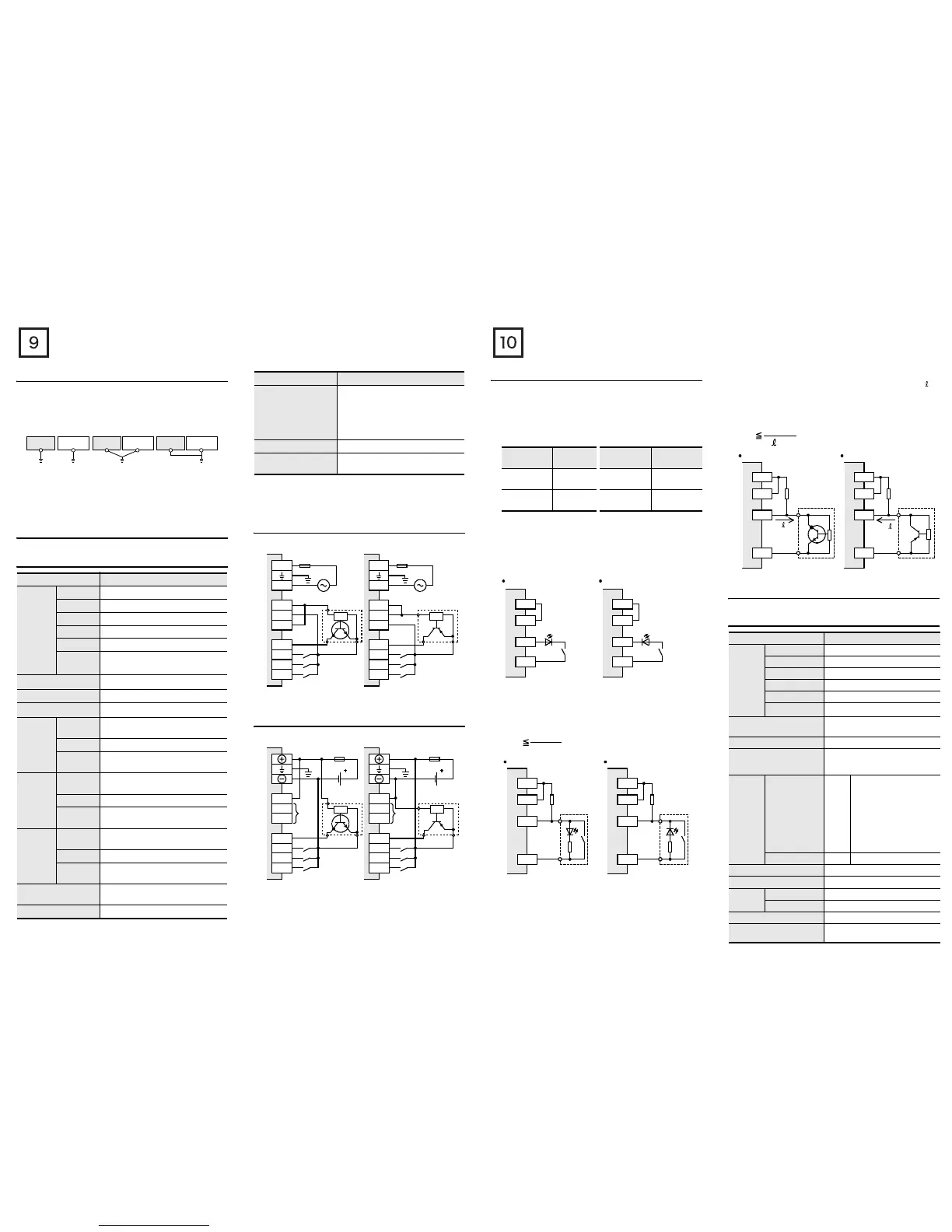
3.4.2 Examples of input wiring[AC power type]
3.4.3 Examples of input wiring[DC power type]
Item Specification
Number of
input
points
FX
3U
-16M
8 points
FX
3U
-32M
16 points
FX
3U
-48M
24 points
FX
3U
-64M
32 points
FX
3U
-80M
40 points
FX
3U
-
128M
*
1
64 points
Input connecting type
Removable terminal block (M3 screw)*
2
Input form Sink/source
Input signal voltage
24V DC +10%, -10%*
3
Input
impedance
X000 to
X005
3.9kΩ
X006, X007 3.3kΩ
X010 or
more
4.3kΩ
(Does not apply to FX3U-16M
.)
Input
signal
current
X000 to
X005
6mA/24V DC
X006, X007 7mA/24V DC
X010 or
more
5mA/24V DC
(Does not apply to FX3U-16M.)
ON input
sensitivity
current
X000 to
X005
3.5 mA or more
X006, X007 4.5 mA or more
X010 or
more
3.5 mA or more
(Does not apply to FX
3U-16M
.)
OFF input sensitivity
current
1.5 mA or less
Input response time Approx. 10 ms
PLC
Another
equipment
PLC
Another
equipment
PLC
Another
equipment
Shared grounding
(Good condition)
Common grounding
(Not allowed)
Independent grounding
(Best condition)
Input signal form
• Sink input:
No-voltage contact input
NPN open collector transistor
• Source input:
No-voltage contact input
PNP open collector transistor
Input circuit insulation Photocoupler insulation
Input operation display
LED on panel lights when photocoupler
is driven.
Item Specification
*
100 to 240V AC
Fuse
L
N
S/S
0V
24V
X000
X001
X002
X003
3-wire type
sencer
*
100 to 240V AC
Fuse
L
N
S/S
0V
24V
X000
X001
X002
X003
3-wire type
sencer
1. Sink input 2. Source input
*Class D grounding
Refer to section 3.3 for details.
*1
Fuse
S/S
(0V)
(24V)
X000
X001
X002
X003
*1
24V DC
Fuse
*1 Class D grounding
Refer to section 3.3 for details.
S/S
(0V)
(24V)
X000
X001
X002
X003
3-wire type
sencer
1. Sink input 2. Source input
24V DC
3-wire type
sencer
*2 Do not connect the (0V) and (24V) terminal with others,
since they are not available.
*2 *2
3.4.4 Instructions for connecting input devices
1) In the case of no-voltage contact:
The input current of this PLC is 5 to 7 mA/24V DC.
Use input devices applicable to this minute current.
If no-voltage contacts (switches) for large current are used,
contact failure may occur.
<Example> Products of OMRON
2) In the case of input device with built-in series diode:
The voltage drop of the series diode should be approx. 4 V or
less.
When lead switches with a series LED are used, up to two
switches can be connected in series.
Also make sure that the input current is over the input-sensing
level while the switches are ON.
3) In the case of input device with built-in parallel resistance:
Use a device having a parallel resistance, Rp, of 15 kΩ or more.
When the resistance is less than 15 kΩ, connect a bleeder
resistance, Rb, obtained from the formula as shown in the
following figure.
4) In the case of 2-wire proximity switch:
Use a two-wire proximity switch whose leakage current, , is
1.5 mA or less when the switch is off.
When the current is 1.5 mA or more, connect a bleeder
resistance, Rb, obtained from formula as shown in the following
figure.
3.5 Relay output specifications and example of
external wiring
→ Refer to FX3U Series User's Manual - Hardware Edition.
3.5.1 Relay output specifications
*1 FX3U-128M does not have DC power supply.
*2 FX3U-16M terminal block cannot be installed/removed
Type
Model
name
Type Model name
Microswitch
Models Z, V
and D2RV
Operation
switch
Model A3P
Proximity
switch
Model TL
Photoelectric
switch
Model E3S
X
0V
LED
24V
S/S
Sink input
X
24V
LED
0V
S/S
Source input
X
24V
0V
S/S
Source input
Rp
Rb
X
0V
24V
S/S
Rp
Rb
Sink input
15 k
Ω
or more
15 k
Ω
or more
Rb
4Rp
15-Rp
(k
Ω
)
Item Specification
Number of
output
points
FX3U-16MR/
8 points
FX3U-32MR/
16 points
FX3U-48MR/
24 points
FX3U-64MR/
32 points
FX3U-80MR/
40 points
FX
3U
-128MR/ES*
1
64 points
Output connecting type
Removable terminal block
(M3 screw)
*
2
Output form Relay
External power supply
30V DC or less
240V AC or less ("250V AC or less" if
not a CE, UL, cUL compliant item)
Max. load
Resistance load
2 A
/point
The total load current of
resistance loads per
common terminal should be
the following value or less.
• 1 output point/common
terminal: 2 A
• 4 output point/common
terminal: 8 A
• 8 output point/common
terminal: 8 A
Inductive load 80VA
Min. load 5V DC, 2 mA (reference value)
Open circuit leakage current -
Response
time
OFF→ON Approx. 10 ms
ON→OFF Approx. 10 ms
Circuit insulation Mechanical insulation
Display of output operation
LED lights when power is applied to
relay coil.
I
X
24V
0V
S/S
Source input
Rb
X
0V
24V
S/S
Rb
Sink input
2-wire
proximity
sensor
2-wire
proximity
sensor
I
I
Rb
6
I
-1.5
(k
Ω
)

 Loading...


