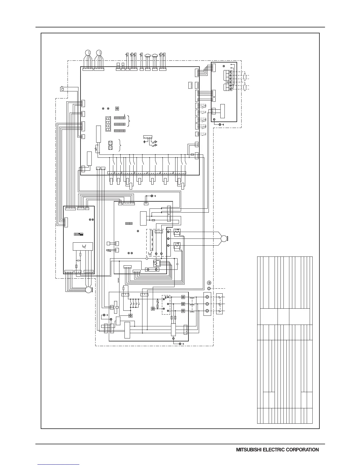
PURY-HP72, 96TKMU-A-H(-BS)
For opening/closing the bypass
circuit
Terminal
block
Central control transmission
cable
Power supply
Function setting connector
IPM temperature
Heat exchanger outlet pipe temperature
ACC inlet pipe temperature
Discharge pipe temperature
Thermistor
SV9
TB1
TB3
TB7
TH4
TH5
TH6
THHS
Z24,25,26
DC reactor
Current sensor(AC)
Low pressure
Discharge pressure
High pressure protection for the
outdoor unit
Pressure
switch
Pressure
sensor
Explanation
Explanation
4-way valve (Cooling/Heating switching)
For opening/closing the bypass circuit
under the O/S
Solenoid
valve
Solenoid
valve
DCL
LEV5a
ACCT1,2
63LS
63HS1
63H1
<Symbol explanation>
Symbol
Symbol
21S4a
C1
DCCT1
SV1a
SV5b
Outdoor unit heat exchanger
capacity control
SV4a,b,d
Subcooled liquid refrigerant
temperature
*1. Single-dotted lines indicate wiring not
supplied with the unit.
*2. Dot-dash lines indicate the control box
boundaries.
*3. Refer to the Data book for connecting
input/output signal connectors.
*4. Daisy-chain terminals (TB3) on the outdoor
units in the same refrigerant system together.
*5. Faston terminals have a locking function.
Make sure the terminals are securely locked
in place after insertion. Press the tab on
the terminals to removed them.
*6. Control box houses high-voltage parts.
Before inspecting the inside of the control box,
turn off the power,keep the unit off for at
least 10 minutes, and confirm that the voltage
at both ends of the main capacitor (C1) has
dropped to DC20V or less.
X001
For inrush current preventionR1
Choke coil (for high frequency noise reduction)L
Indoor/Outdoor transmission cable
Magnetic relay (inverter main circuit)72C
Heat exchanger capacity control
Linear expansion valve (for the control of
evaporating temperature)
Resistor
For current detection
RSH01
Capacitor (inverter main circuit)
Current sensor(DC)
For opening/closing the injection circuitLEV4
For opening/closing the defrost circuit
SV10,11
OA temperature
TH7
TH9,11
Ground
L3L2
L1
X14
X13
6
1
3
5
12
red
CNPS
1
3
2
1
TP1 TP2
TB3
2
3
TB7
M1 M2 M1 M2 S
512 34
1
2
t
°
1
2
132
3
4
6
1
2
2
CN82
blue
1
3
4
CN83
black
31
6
X12
1
3
CN508
blue
CN4
black
231
t
SW001
1
3
°
CN2
7
12
1
3
31
432
2
3
1
1
TH4
t
4
°
1
1
CN211
green
23
123
321
6
CNSNR
5
4
3
2
1
U
V
W
Fan motor
(Heat exchanger)
MS
3~
4
1
6
CNINV
2
SW1
1
6
OFF ON
3
2
23
Power failure
detection circuit
red
1
Surge
absorber
2
3
1
TB1
L3L2L1
21
INV Board
°
t
2
L
yellow
CNPOW
t
°
654
5
CNVDC
4
CNDC2
1
ACCT2
F02
AC250V
3.15A T
C1
IPM
4
X10
ON
X08
Unit address
setting
LED3:Charge
6
3
1
6
F001
AC250V
6.3A T
F002
AC250V
6.3A T
RSH01
CN001
531
TB22 TB23TB21
Diode stack
~~~
12
34
3
green
CN62
CN990
green
CNTYP4
CN201
Z25
1
TH5
2
SWU2
LED1
SW6
10
Control Board
CN40
63HS1
CN41
TH7
15
5
4
3
1
SW4
LED3
2
LEV5a
3
SET UP(SW6-10)
V
M
OFF
CN506
red
yellow
CN3K
*3
Compressor ON/OFF output
Error detection output
DC12V
CN51
SV5b
W
blue
CN3N
1
3
3
4
TB7 Power
selecting
connector
CNVDC
IPM
5
1
26
ON
OFF
M-NET power
supply circuit
12
M-NET Board
Power failure
detection circuit
Indoor/Outdoor
transmission
cable
ON
1's
digit
CN102
1
4
1
U
10's
digit
OFF
LED2:Normal operation(Lit)
/ Error(Blink)
yellow
CNDC
red
MS
3~
2
TH6
U
LED1:Power supply to
Indoor/Outdoor
transmission line
ZNR400
Central control
transmission
cable
ONOFF
Motor
(Compressor)
red
CN3S
1
CN04
red
CN43
yellow
CN61
green
CN202
red
8
/ Error(Blink)
*4
2
P
63H1
4
1
SW5
10
5
CN3D
1
CPU power
supply circuit
black
CNAC2
1
*3
ONOFF
10
SWU1
N
CN212
red
WU
P
6
CNDC1
1
4
V
1
CN80
25
F301
AC250V
15A T
CNIPM
CNTYP5
green
LED4:CPU in operation
FT-N
LED1:Normal operation(Lit)
/ Error(Blink)
CN801
red
SWP1
CN012
1
3
FAN Board
63LS
U
-
+
ZNR005
Z24
2
CN507
black
3
F003
AC250V
6.3A T
TB42
6
4
X001
CN213
green
black
*5
SV9
Function
setting
LED1
Display
setting/
Function
setting
red
LED4:CPU in operation
5
1
SC-P1
DCL
black
CN72C
red
3
1
DCCT1
1
2
1
4
1
CNLVA
1
CNR1
red
black
F01
AC250V
3.15A T
TB31
R1
white
red
CNIT
red
X001
12
Power Source
3~
60Hz
208/230V
CNCT
red
white
ACCT1
56
CN110
Noise filter
31
6412
IPM power
supply circuit
CNFG2
Noise
Filter
black
4
3
2
1
CNCT2
blue
4
3
2
1
X05
X06
3
5
1
6
CN505
13
12
CNFG
blue
1
2
black
redwhite
*5
black
red
THHS
°
t
Z26
CNTYP
2
CNTH
green
21
CN110
black
2
1
red
1
2
1
CNAC
CN81
green
12
5
1
3
4
4
SV4a
4
CN2
C310,C311
SV4d
SV1a
SV4b
21S4a
1
2
3
4
6
M
CNLVE
yellow
LEV4
TH9
TH11
t
°
2
CN509
yellow
CNS2
32
3
1
X04
yellow
CN504
SV11
3
1
X03
green
CN503
SV10
CN72C
green
LED1:Normal operation(Lit)
 Loading...