2-17 Outside dimensions ・ Operating range diagram
2 Robot arm
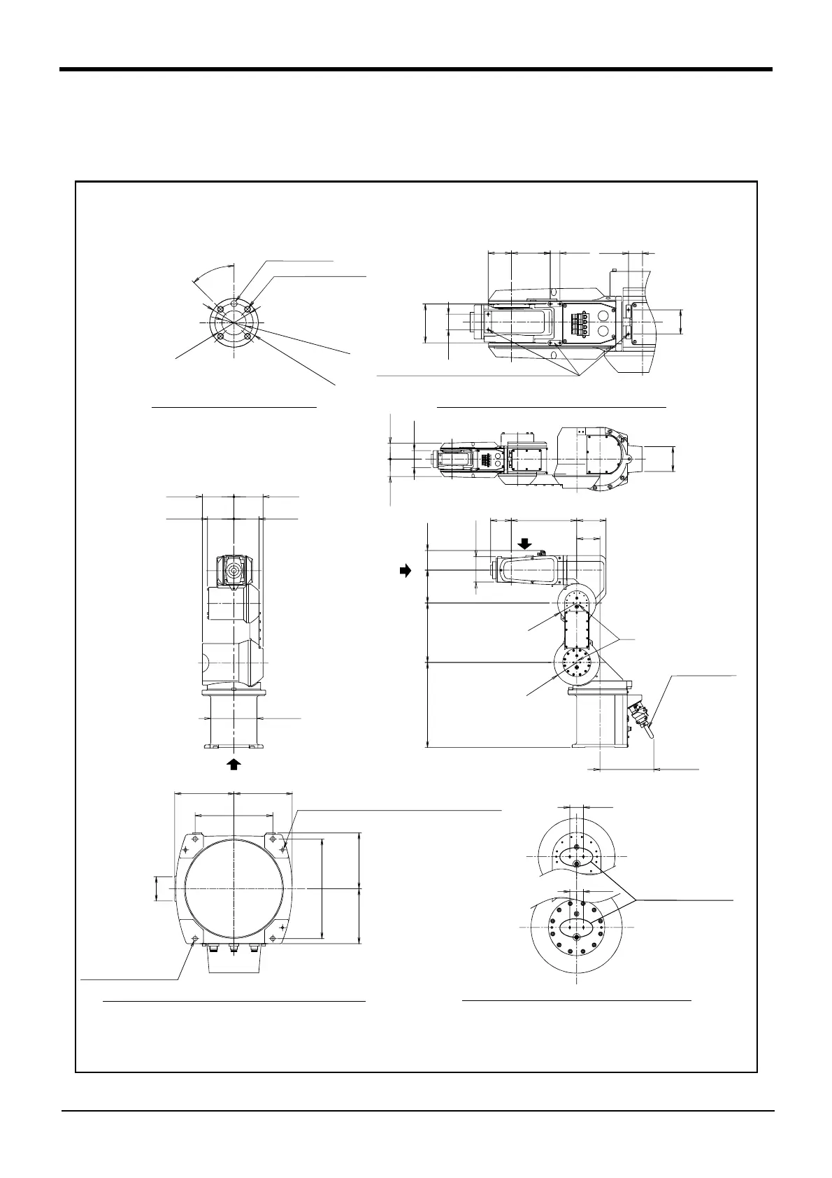
2.4 Outside dimensions ・ Operating range diagram
(1) 6-axis type
The type in which all axes have the brake is also the same.
Fig.2-3 : Outside dimensions: (6-axis type)
A
C
350
81
135
245
*
85
270
95
R
9
4
105
120
R
7
9
230
D
* Dimensions when installing a solenoid valve (optional)
Machine cable
(Maintenance space)
28
28
Screw holes for fixing
wiring hookup (M4)
View D: Detail of screw holes for fixing wiring hookup
(for customer use)
65
72
φ70
102
80
32
48
50
80 20 29
View C: Detail of screw holes for fixing wiring hookup
Screw holes for fixing wiring hookup (M4)
(for customer use)
130
120
φ190
B
104109
4
5
°
φ
3
1
.
5
φ
2
0
H
7
d
e
p
t
h
8
.
5
φ
4
0
h
8
d
e
p
t
h
6
.
5
View A: Detail of mechanical interface
4-M5 screw, depth 9
φ5H7 depth 9
115
113
205
122
120
50
160
6.3a (Installation)
4-φ9 installation hole
6.3a (Installation)
View B bottom view drawin
: Detail of installation dimension
2-φ6 (prepared holes for φ8 positioning pins)
*1)
*1) The depth in which the screw is tightened is 7.5 to 8.5mm.
 Loading...

