2-31 Options
2 Robot arm
■ Cable configuration
The configuration of the flexible cable is shown in Table 2-15. Refer to this table when selecting the cable bare.
Table 2-15 : Cable configuration
Note) The square in the cable name indicates the cable length.
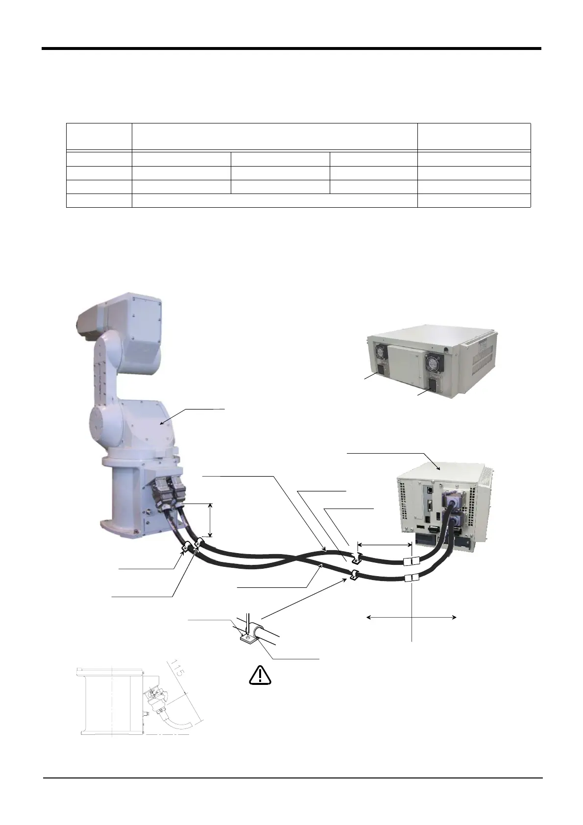
■ Fixing the flexible cable
(1) Connect the connector to the robot arm .
(2) Wind the silicon rubber around the cable at a position 300 to 400 mm from the side of robot arm and exten
-
sion section as shown in Fig. 2-11, and fix with the nylon clamp to protect the cable from external stress.
Fig.2-11 : Fixing the flexible cable
Item
Motor signal cable
1S- □□ LCBL(S)-01
Motor power cable
1D- □□ LCBL(P)-02
No. of cores
AWG#24(0.2mm
2
)-4P AWG#24(0.2mm
2
)-7P AWG#18(0.75mm
2
) AWG#19(0.75mm
2
) -3C
Finish dimensions Approx. φ6mm Approx. φ8.5mm Approx. φ1.7mm Approx. φ6mm
No.of cables used 5 cables 1 cable 1 cable 10 cables
No. in total 7 cables 10 cables
Silicon rubber
Nylon clamp
300~400mm
NK-14N
NK-14N
NK-18N
1D-□□LCBL(P)-02
1S-□□LCBL(S)-01
Nylon clamp
Robot arm
Nylon clamp
Nylon clamp
CR1B-571 controller
NK-18N
The fixed cable 5m
(standard attachment)
Extended flexible cable
(optional)
Extension section
Nylon clamp
300~400mm
Cover the extension terminal area with
the cover etc. so that it may not be
easily touched to the latch lever.
CAUTION
The cable shall bend and size shall be
115mm or more.
DU1A-700 series Drive unit
Drive unit
DU2A-700 series
CN1
CN2
 Loading...

