3 Controller
Standard specifications 3-40
3 Controller
3.1 Standard specifications
3.1.1 Standard specifications
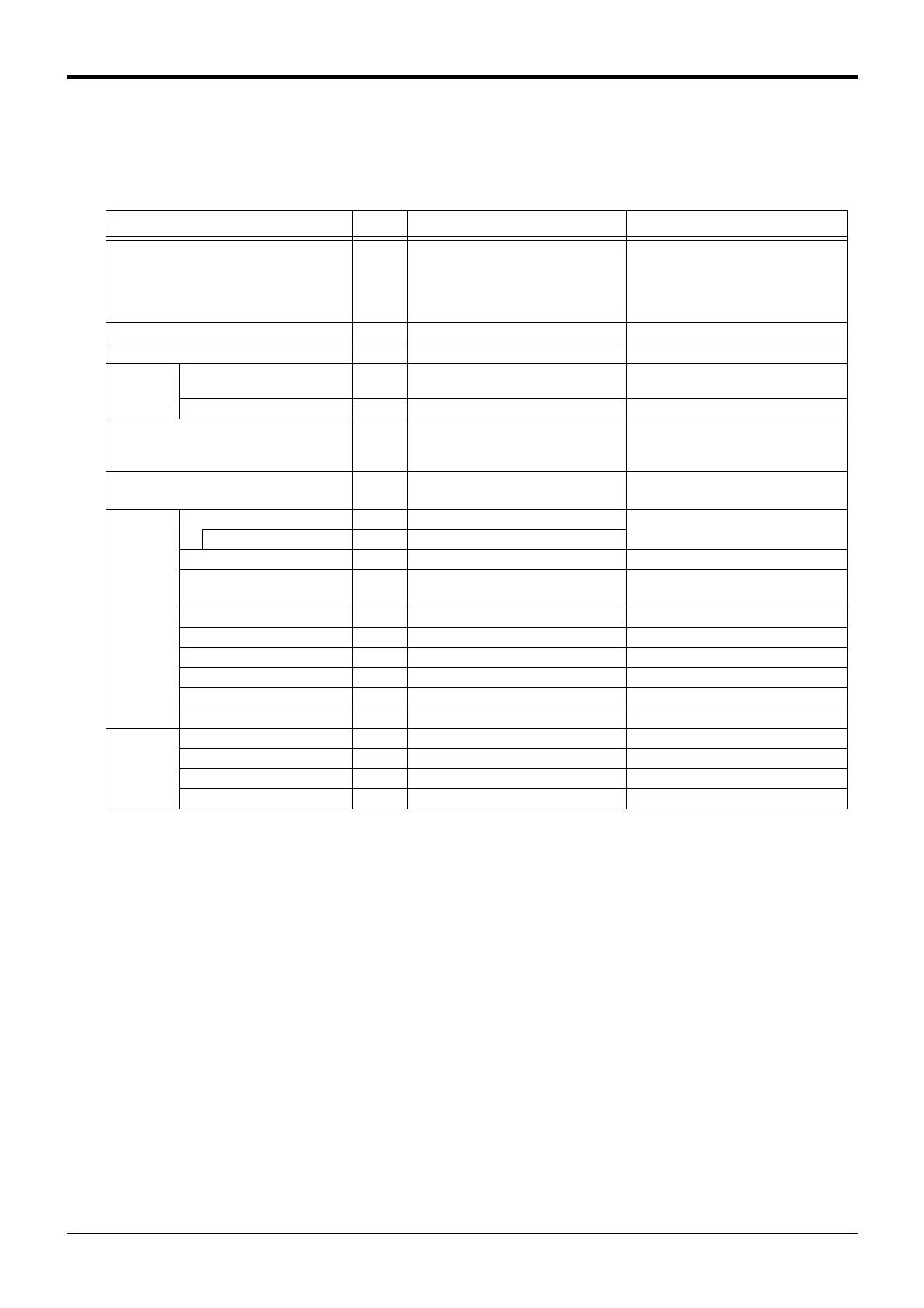
Table 3-1 : Standard specifications of controller
Item Unit Specification
Remarks
Type
CR1QA-700
or
CR2QA-700
Note1)
RV-3SQ series:
CR1QA-721/CR2QA-721
RV-3SQJ series:
CR1QA-731/CR2QA-731
Note1) The controller of CE Marking specification
*"-S12" specification: the controller is CR1QA-700 series.
*"-S312" specification: the controller is CR2QA-700 series.
Number of control axis Simultaneously 5/6(Maximum)
CPU 6 4 bit R I S C / D S P
Memory
capacity
Programmed positions and No.
of steps
point
step
13, 000
26, 000
Number of programs 2 5 6
Robot language M E L F A - B A S I C V
or
ME L F A - BAS I C IV
Note2)
Note2)The program of MELFA-BASIC IV can be used by MELFA-BASIC V, if program is converted by RT ToolBox2 (option).
Teaching method Pose teaching method, MDI
method
Note3)
Note3)Pose teaching method: The method to register the current position of the robot arm.
MDI method: The method to register by inputting the numerical value Immediate.
External
input and
output
input and output point Input 0 point/Output 0 point Multi-CPU share device
Input 8192/Output 8192 (Max.)
Dedicated input/output Assign to the multi-CPU share device.
Special stop input point 1
Hand open/close input/output point Input 8 point/Output 0 point
Up to 8 output points can be added as an
option
Note4)
Note4)It is when an pneumatic hand interface (2A-RZ365/2A-RZ375) is installed.
Emergency stop input point 1 Dual line, normal close
Door switch input point 1 Dual line, normal close
Enabling device input point 1 Dual line, normal close
Mode output point 1 Dual line
Robot error output point 1 Dual line
Addition axis synchronization point 1 Dual line
Interface RS-422 port 1 Only for the teaching pendant
Ethernet port 1 : Only for the teaching pendant 100BASE-TX
Hand dedicated slot slot 1 Dedicated for pneumatic hand interface
Additional axis interface Channel 1 SSCNET Ⅲ
 Loading...

