5-214
5.12 Standard Timer Function Blocks
5.12.4 Timer function blocks
TIMER_10_FB_M
5.12.4 Timer function blocks
TIMER_10_FB_M
Function
Operation processing
(1) TIMER_10_FB_M
(a) Starts measuring the current value when the executing condition of turns ON.
Starts measuring from the value input to 10ms, and when the measuring value
reaches to the value input to 10ms, turns ON.
The current value is output from .
(b) When the executing condition of turns OFF, the current value is set to the value input
to , and turns OFF.
*1: The first five digits of the serial number are '04012' or higher.
TIMER_10_FB_M
TIMER_100_FB_M
TIMER_HIGH_FB_M
TIMER_LOW_FB_M
TIMER_CONT_FB_M
TIMER_CONTHFB_M
indicates any of the following
functions.
TIMER_10_FB_M
TIMER_HIGH_FB_M
TIMER_CONT_FB_M
TIMER_100_FB_M
TIMER_LOW_FB_M
TIMER_CONTHFB_M
Input argument, s1:
Executing condition (TRUE: Execution, FALSE: Stop) :Bit
s2:
Timer setting value :Word (signed)
s3:
Timer initial value :Word (signed)
Output argument, d1:
Timer current value :ANY16
d2:
Output :Bit
Universal
UD
High
Performance
* 1
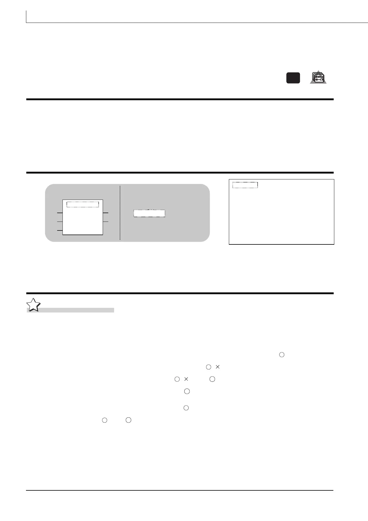
ST
Structured ladder
s1d1
d2s2
s3
TIMER_10_FB_M
(s1, s2, s3, d1, d2)
CAL
TIMER_10_FB_M
s1
s3
s2
d2
d1
s1
s3
d2
 Loading...


